Hello,
This is my first post on this great forum. I’m very
interesting in Bomber Command history and its planes. One member of my family was an airman in 300 (Polish) Heavy Bomber Squadron during the war and so the history of BC is so home to me. For some time I create digital images that show Bomber Command planes in action.
What I did till now was based on the Len Deighton story “Bomber” (here is the link with examples http://www.flickr.com/photos/97107932@N00/sets/72157594216829249/ ).
Right now I’m creating 3d model of Short Stirling Mk III bomber for the new series of images (here is the link to the forum where I’m showing the finished first stage of building of this plane: http://www.max3d.pl/forum/showthread.php?t=35524
Unfortunately it’s very, very hard to get good references, plans and good quality photographs. Most of the time I’ve spent on analyzing how each and every part looks like. There are a lot of mistakes in the model (FN5A turret should be frameless etc.).
I’m looking for some drawings, photographs of the parts of this plane marked with red (in attachement), especially the bottom of this plane – flaps (how they worked in this plane), engine number 2/3 bottom area (view with closed undercarriage covers) and windshield area.
Can anyone help?
Thank You
Peter

By: stirling01 - 31st March 2025 at 14:34
Short Stirling Mk III cockpit clock
Can anybody tell me the exact place of the clock in the Short Stirling MK III cockpit ? Was it a clock like the one in the Spitfire or with a somewhat smaller dial (ref.nr.?) A picture would be great.
Rijnko
By: 12jaguar - 31st March 2025 at 14:33
Ours has the stopwatch holder in the approximate location that you described ie to the left of the magneto switches (at least that’s where it’s going to be)
By: stirling01 - 31st March 2025 at 14:33
Hi John,
I did so, but that is the problem. I cannot find a clock at all in my pilot’s notes Stirling Mk I,III,IV. On pictures in books you see sometimes a clock or only a stopwatch on different places. Before I make the holes in the panel I would like to know if they are on the right place and for what clock, but that seems rather difficult. I think the best place is on the left side next to the longdolly ignition switches in the center and for the clock with the smaller dial with square backplate
Rijnko
By: 12jaguar - 31st March 2025 at 14:33
Hi Rjinko
In my experience (limited though that may be:rolleyes:), I’ve yet to see 2 instrument panels that are identical. We’ve based our panel on a photo taken at the Shorts factory, but if you look at Hindenburgs, his layout is completely different. If you want a generic panel,try the illustration in the Pilot’s Notes.
John
By: stirling01 - 31st March 2025 at 14:32
Yes, John that is the correct place for the stopwatch, I think.
I have often seen the stopwatch on that place, but souldn’t there also be a clock in the cockpit or did the pilot have to look on his wristwatch ?
You sometimes see a clock above the right magnetoswitches, between the D.R. switches and the Undercarriage masterswitch. On the other hand you also see sometimes,on later Stirlings, a blank square plate on the location of the stopwatch just the size of the backplate from the clock with the smaller dial. So rather confuzing. I am not sure what is best at the moment.
Rijnko
By: stirling01 - 31st March 2025 at 13:56
Had a look today in Michael J.F.Bowyer’s book The Stirling Story and on page 168 is a cockpit-picture of a MK III Stirling. There is a stopwatch and a clock with small dial just like Hindenburg’s panel. So I’m going to fix my Mk II c clock, ref.nr.6A/1104 on the same place and hope to purchase a stopwatch and stopwatch-holder soon to add to the panel..
Rijnko
By: Gavin.H - 31st March 2025 at 13:40
This won’t help much but I would love to know it’s identity. The serial isn’t visible on the original,
Cheers
John
Hi John, Great photo! I can’t help you much with the identification of this Stirling but do you know where this was taken? In my humble opinion I would suggest that this is taken from South Marston where they were produced/repaired.
So very few pictures out there of this fantastic aircraft, lovely to see your pic!
Gavin
By: John Aeroclub - 31st March 2025 at 13:39
Hi Gavin
I now believe it has something to do with 214 Sqn. A chance encounter and a conversation, with an old friend at another friends funeral, about the war memorial suddenly triggered the name of the lady who gave me the photo of her late sons aeroplane nearly 50 years before. The airman who died was Sgt Walter Perkins and he was lost in a Flying Fortress of 214 over Germany on an ECM mission. I think the a/c is possibly BU.T and possibly Downham market.
John
PS I have only just realised it’s missing it’s u/c doors?
By: Icare9 - 31st March 2025 at 13:36
Hi, John It’s definitely coded “T” on the nose, but it could be a letter near the crew door that appears to be a “C” or a “G”, not a “U”
For it to be 214, that would make it later than Oct ’42, or after Dec ’43 if Downham Market.
Trees etc in background look in full foliage and the Stirling doesn’t look “tired”.
You may well be correct, but I’d welcome more expert opinions.
By: John Aeroclub - 31st March 2025 at 13:36
Yes the a/c letter is T and the odd thing about 214 a/c is that they carried the a/c letter in front of the roundel and the Sqn codes aft. I have had a glass on the original picture and I think that the letter visible between the u/c components is T and that the B is just disernable between the roundel and the door, with the U painted mostly on the door. This is illustrated quite well in the picture of a 214 a/c (Q.BU) carried on page 17 of the Warpaint publication.
John
By: Bluebird Mike - 1st June 2007 at 12:20
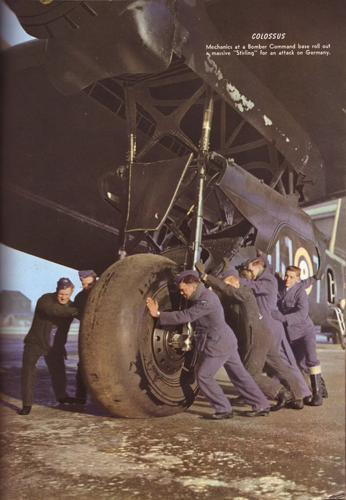
That colour picture of the 149 squadron Stirling being ‘pushed’ is very familiar to me; I have an original B&W copy of that, which my Grandad (who was ground crew on that squadron throughout the war) acquired at the time. He’s not in the photo, he kept out of shot- just as he did when ‘Target For Tonight’ was being filmed. If only he’d been in it! 😮
By: 12jaguar - 1st June 2007 at 12:07
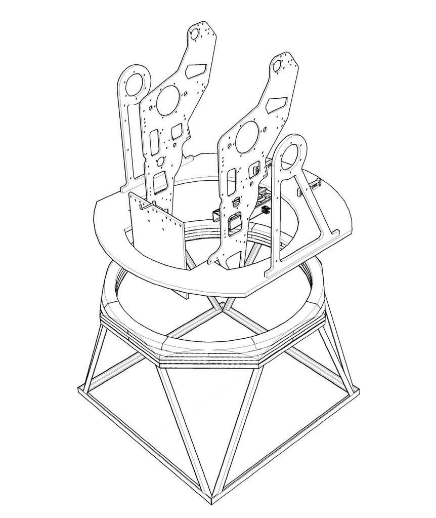
Further to previous responses, the FN5 series of turrets were hydraulically fed from above through a rotating service joint attached to the vertical hoop structure. The pressure and return pipes were routed down the inside of the hoop then forward to the motor, rams etc. The Mid upper turrets were fed from underneath, thus negating the service joint and allowing for greater simplicity and visibility in that area. The simplified hoop acts as the mounting for the gun sight and various electrical anciliary equipment.
Hope this helps
John
By: turretboy - 12th March 2007 at 01:36
MrBlueSky,
Thank you for tarting up my scan, it looks great!
Cheers,
By: CSheppardholedi - 7th March 2007 at 21:07
Less stress on the control cables and rods if held in place outside. A/C don’t like wind from the wrong direction whilst sitting on the ground. Can do nasty things even if they don’t get airborne! Think of how much wind an elevator or rudder can catch, on something as big as the Stirling…you have a big bunch of trouble.
By: DocStirling - 7th March 2007 at 19:21
These were control locks to prevent the wind from whipping the surfaces around. They were not put on unless conditions dictated it or if the aircraft was in storage.
Deryck
I thought as much, but would it not have been easier to lock the controls from inside the cockpit?
DS
By: Deryck - 7th March 2007 at 14:36
The ‘bands’ over the control surfaces
These were control locks to prevent the wind from whipping the surfaces around. They were not put on unless conditions dictated it or if the aircraft was in storage.
Deryck
By: DocStirling - 6th March 2007 at 22:31
Whilst we are on the subject…..:o
Anyone know what the ‘bands’ are for around the wings and stabiliser on this picture, from Peter van Gelderen’s excellant Stirling Pages?
Do they prevent the ailerons/rudder moving in the wind:confused:
DS
By: MrBlueSky - 6th March 2007 at 19:09
turretboy
I liked your scan so much I decided to tart it up for you… Hope you like the results;)
By: f_peter - 6th March 2007 at 05:47
It’s absolutely amazing, how Wide and Great is Your knowledge in this subject! Thank You all for HELP!!! I didn’t realised how professional this forum is! All Your posts are so helpful!!!
@Pondskater> thank You for further informations and explanations 🙂
@682al> Thank You very much for photos and informations. This is exactly what I wanted to know 🙂 Excellent photos!!!
@Cees Broere> Thank You for the informations
@MrBlueSky> Thank You for the photos. I already know them, BUT not in this quality. Now I see so many details!!!Thank You 🙂
@turretboy> WOW!!! The scans are just G-R-E-A-T. So many details are visible now. I admire Your work on restorations the turrets!!! Excellent!!! Thank You VERY MUCH!!!
By: turretboy - 6th March 2007 at 02:49
Hi Peter,
Your work is very impressive!
I have been working on a model of a FN121 turret with Acad 2007. I haven’t yet detailed the accommodation plate so the vertical frame members aren’t in their exact locations.
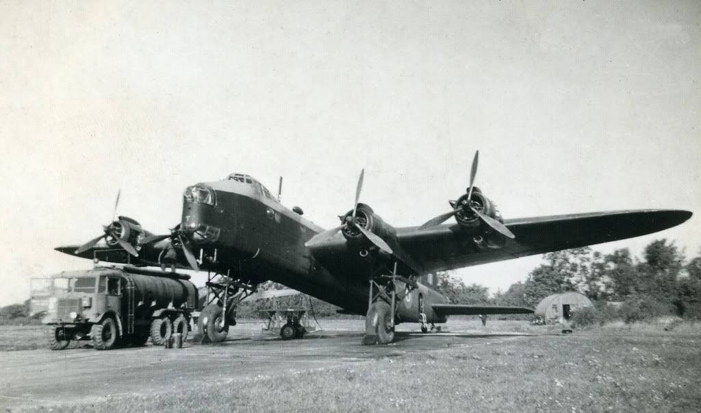
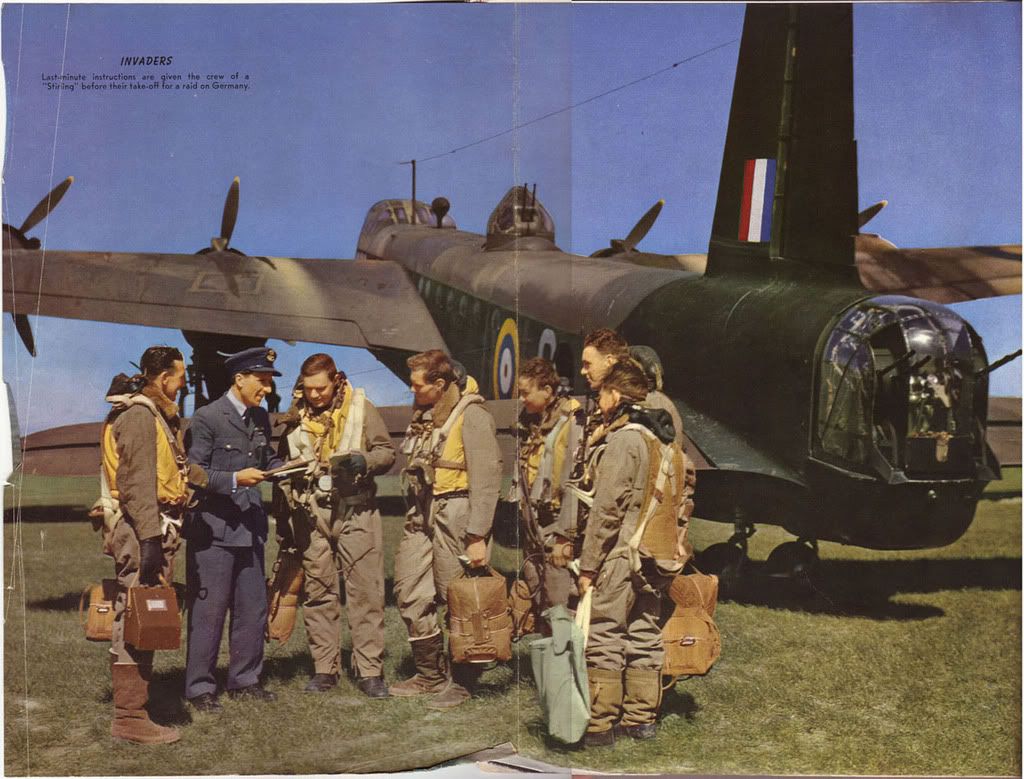
I managed to find and scan two pages from the Sept 1942 edition of “Flying”.
My guess of the first image is an early Stirling, with a FN4 tail and FN7 mid upper turret. The second certainly shows how massive the undercarriage was.
I hope they are of some use to you.
Cheers,


 Sign In
 March 1, 2007 at 3:48 pm