This is for my CAD Lanc project and is about the fit of stringers within former/frame slots. I don’t think the past 70 years have made much difference to the placing of stringers in frame slots
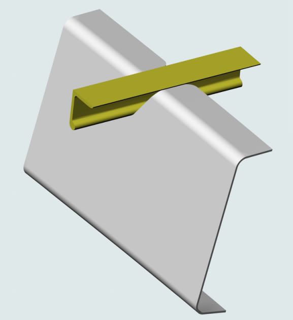
I have not been able to find cross-section dimensions for the stringers in the nose section of the Lanc. But I do have the dimensions of the slots.
It seems to me that the slot dimensions could give a good approximation for the stringer values. It comes to a question of how closely the stringer cross-section fills the slot.
So here are two possibilities: a tight fit and a slack fit. Which is correct or which is the closest? Or is it just in between?
I suppose there are two questions. Does the stringer bead go right to the bottom of the slot? Does the stringer tongue fill the top of the slot?
slack fit
tight fit
Many thanks, folks.
Mike

By: MikeHoulder - 25th August 2011 at 19:54
I’m slow today
Smirky, I’m still not sure what you mean. The following is my understanding of the structure in this area:
The front windscreen frame is fixed via the gussets mentioned previously to the top of the box section of Former/Frame E and the cockpit side rails. Possibly also to the top of the top stringer running between Former/Frames E, F, G.
The bare instrument panel is fixed to the rear of the box section of Former/Frame E. The top of the instrument panel is flush with the Former.
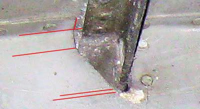
The only thing left to my understanding are the exterior strips for the nose of the windscreen frame as arrowed (faintly) in the attached photo.
Please come back to correct me.
Mike
By: smirky - 25th August 2011 at 00:28
Mike, I’d forgotten about those bits – I think Malcolm mentioned them to me. I willl email him myself about that.
It was the sheet metal band that goes across the top of the nose from just in front of frame E following the line of the windscreen back to the cockpit side rails just in front of frame D that I was asking about.:)
(I have got the instrument panel and some copies of the flat front windscreen panels and I am trying to fill the gap.)
By: MikeHoulder - 24th August 2011 at 14:35
Formers & gussets
Smirky, frames 17,18,19 looking aft have the right sheet gauge 18,10,10.
The only problem is that my source giving the direction of the frames has 17 & 18 facing aft as per your photo; but 19 facing forward. I think I’d accept an error in my source. It is a low grade scrap perspective drawing. Add to that, frame 17 from original documentation has a radius on the corners of the frame of 1/8″ rather than the 13/64″ shown in the drawing I included in my last post. That squares better with my first attempt to extract dimensions from your photo.
You mean the triangular cross-section gussets fitted along the top of frame E that take up the angle of the front deck to give a horizontal base along the width of the windscreen?
Since my original intention was to do the nose section stopping at frame E, I haven’t yet done a search for documentation of these. However Malcolm Goosey sent me two splendid photos of his casting of the gussets in February. For my sake, you are welcome to these. But I’d better ask Malcolm’s permission. Send me a PM with some details of yourself and your project that I can forward to Malcolm.
My best wishes
Mike
By: smirky - 24th August 2011 at 00:08
After a lot of head scratching, I think we are looking aft at frames 17, 18, 19.
(This is the section of W4964 on display at Newark Air Museum.)
I want to make the complex shaped strip of metal that fits the bottom of the windscreen frames to Frame E – can you help with a drawing?
By: MikeHoulder - 23rd August 2011 at 20:36
Thanks
Yes, it does help, Smirky. Thank you very much.
The formers in your photo seem to come from the centre or the rear centre section of the Lanc. All formers in these two regions, except transport joints, are made with either 18 gauge (1.024 mm) or 10 gauge (2.588 mm) Alclad sheet. The former nearest the camera is 18 gauge; the next is 10 gauge, the third is either 18 or 10 gauge. I’m not sure of the last.
All three formers are facing the same way. That should have been enough to identify the formers 100%. The best I can do is to identify them probably as formers 23, 22, 21 looking to the front. Do you know better?
Here are some pics to show you what I am doing to extract the data I need:
A section from a Lancaster engineering drawing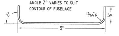
A framework to apply known dimensions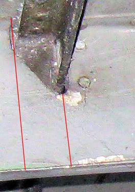
Angle Z in this case is 90 degrees. I need to think a bit more before deriving the numbers – tomorrow’s job.
Best wishes
Mike
By: smirky - 22nd August 2011 at 16:44
does this help?
[ATTACH]199010[/ATTACH]


 Sign In
 August 22, 2011 at 3:43 pm