‘Black Dog’ in the Churchillian sense!
First a definite mistake in Avro drawing D2310. The heights of Frame H in the drawing do not correspond to the given values of 20 21/32 and 28 5/16. The height below the datum line should be about 3/4″ greater in the drawing. I counted the pixels in an unaltered version of D2310 for both heights and the ratio of pixels does not correspond to that of the given values.
This pic illustrates the problem.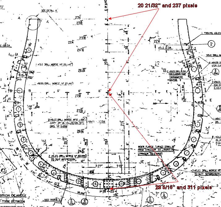
It will be a ****** to get the bottom curve right to allow for the extra 3/4 height”.
Point 2, this is where I have the most trouble. Here’s a pic: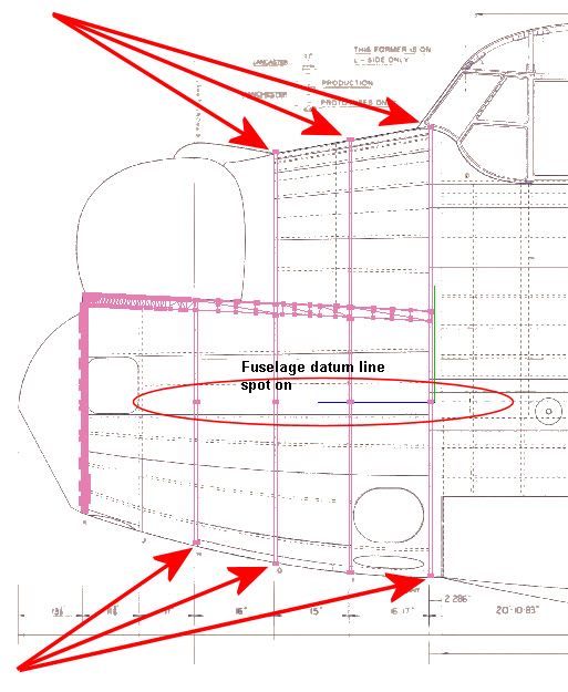
As the backdrop I am using an unaltered section of the best Avro nose section drawing I have. The end points, top and bottom, of frames H, G and E do not correspond to the Avro drawing. I’ve taken the greatest possible care over the dimensions of these frames and the individual frame datums are lined up perfectly with the fuselage datum. I am tempted to say the Avro drawing is in error. Particularly the bottom curve from E to K is not as it was drawn. The original drawing was a very big one and before the arrival of CAD it would have been impossible to check the curve.
Point 3, this is a good one. Here’s a pic: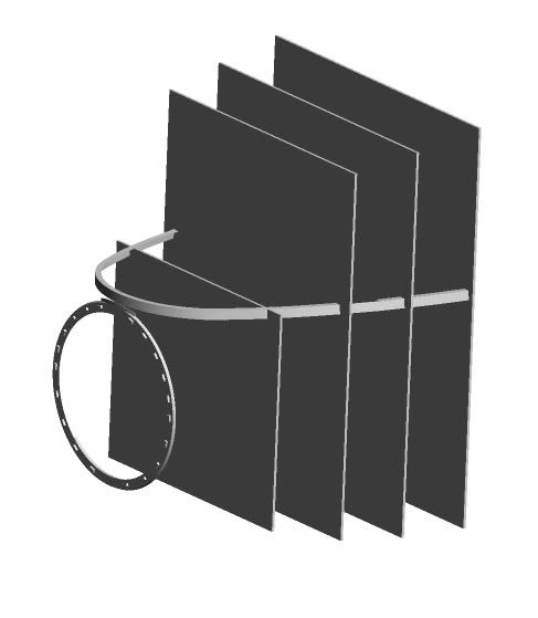
At least the longeron lines up well with frame slots. The boxes are the enclosing boxes which have the maximum dimensions of the corresponding frames. It will line up even better when I put in the kink on the longeron between frames G and F.
Thinking about Point 2 again. The only thought I have is that the box for frame G does not allow for the cutout of the escape hatch. If the front/back curve of the escape hatch is shallower than anticipated, I’m alright there. But the curve between H and K is shallower than shown in the Avro drawing.
Now I sent all this to Geoff in an email and, great thanks to him, he replied almost immediately. He sent me in return 2 emails:
The first started “mike i noticed this problem the other day…”
The second “SEE DRAWINGS NOS.”
I’d better let him post his emails here if he wishes to do so. But, Geoff, thanks a million.
Mike

By: MikeHoulder - 2nd March 2011 at 21:38
Wow! What a difference just using the numbers makes
Here are the numbers. Three of them were illegible in the Avro drawing. I’ve replaced them with the closest fit I could produce. The numbers are in inches.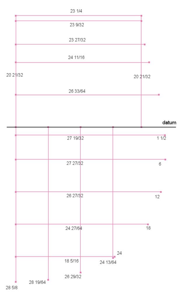
I produced the curve using a spline and a nice Interpolate function. I used some trig etc to produce the inner profile at the correct distance from the outer profile. Here is frame H superimposed on the Avro drawing: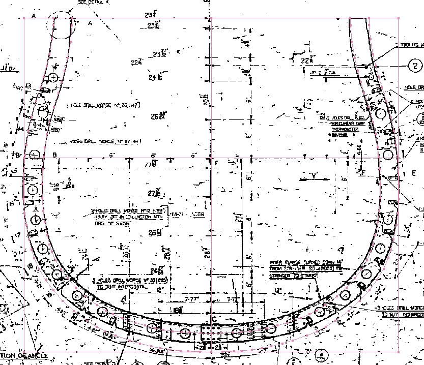
What a difference following just the numbers makes! I wouldn’t have dared depart so far from the Avro drawing without all your comments.
Mike
PS: It’s also solved the problem point 2 in my first post in this thread. Now the bottom of frame H meets the nose profile curve very nicely.
By: MikeHoulder - 2nd March 2011 at 20:44
Yes, I remember the red faces when the video cable couldn’t reach the camera in the front of the fin when they were finishing the installation. But that’s not really the fault of CAD. CAD gives the possibility. It’s up to the designer to use it properly.
Mike
By: Arabella-Cox - 2nd March 2011 at 20:34
CAD isn’t without its faults as well. Can I say this on a Historic aviation thread?…. Airbus A380. 😀
By: DavidS - 2nd March 2011 at 13:21
On the Nimrod I can only refer you to the threads on the decision to scrap. There have been a number of comments that each airframe has its own unique difference. Bear in mind that the fuselage drawings were initially done decades ago. I’d guess that they weren’t redrawn completely when redesigning the Nimrod from the Comet. From the same factory, I do remember the 748 drawings being redone to design the ATP and that also meant a change from imp to metric. Again, I’m not sure that the whole fuselage was redrawn.
It seemed commonplace then but in hindsight amazing to see how many times the fitters had to return to the drawing office as the drawings didn’t reflect a particular aircraft and I’m talking not just Nimmie but Vulcan, Victor, Shack and the other less numerous aircraft Woodford saw. I wonder in these CAD days whether everything fits together perfectly and gives good access for the chaps doing the job?
By: QldSpitty - 2nd March 2011 at 13:16
We have found similar problems with the Spitfire drawings.Numbers not measuring up with whats drawn.Trust the numbers and use CAD to smooth out the shapes.
By: MikeHoulder - 2nd March 2011 at 12:26
Very interesting replies
DavidS, am I correct? You say that there are significant differences in dimensions between individual Nimrod aircraft. Significant, not in operational terms, but in detailed draughting terms.That is, even today, a large complex design cannot be manufactured to a precision of less than some number of mm or cm. Wow! That blows my mind. For my own purposes, I can’t say yet whether that’s good or bad for my own work on the Lanc.
Also what this seems to say is that the jig construction was the most important part of the whole design process. That’s where you come in, aeronut 2008. It seems to me the jig engineers provided a reality check on the design office giving feedback through perhaps several iterations.
Who did the analysis that a particular small fastening, say, was not strong enough to carry its loads and that it needed to be beefed up? From the little I know, the design and stressing offices had insufficient manpower to do this sort of work. I can only believe it was the intuition and experience of the jig engineers that was responsible and who gave the necessary feedback to the design office.
My Lanc project is to understand the Lancaster as completely as I can. Everywhere I look there is an explosion of things to understand or techniques to learn. Now, here is a really major area completely new to me, the jig engineering of the Lanc. I feel this is probably the most important area of all and yet it seems there is a complete lack of documentation or history.
Mike
By: DavidS - 2nd March 2011 at 10:08
Also, don’t forget that a goodly number of drawings will have DOM (Design Office Memo) and DDI (Design Office Instruction) related to them with no mention of these on the drawings. All well and good when on the production line but will cause no end of problems many years later. Though one would have imagined that anything this major would have meant a new issue of drawings. Perhaps we’re seeing a related issue to the Nimrods where each aircraft was different by mm or cm.
Did all manufacturers have the same issue or was it just those in Manchester?
By: Arabella-Cox - 2nd March 2011 at 08:53
Having served my time at the drawing board as a draughtsman before the days of CAD I should be warn you against taking your own dimensions off a drawing.
That’s why drawings had the phrase DO NOT SCALE or NTS on them.
My Grandfather was responsible for altering the outer wing jig drawings for the Manchester to make them into the Lancaster jig, all he did was alter the dimensions between the rib spacing and all the others to suit. Taking a scale rule to the resulting drawing would be a disaster but using the quoted dimensions wouldn’t.


 Sign In
 March 2, 2011 at 2:08 am