I wonder if my work would be of interest. I am working my way through the existing Avro drawings to produce 3D Cad versions of as many of the structural components as I can.
Unfortunately there are very many Avro drawings missing. I suspect I will have to arrange living with a real Lancaster for several months.
The other problem is that the existing Avro drawings are nth generation photocopies that suffer badly from both linear and spherical distortion as well as illegible dimensions. I have done my best to overcome this by logical and pixel analysis, guesswork etc.
The first pic shows how all my parts fit together: frames, stringers, longerons and intercostals, to form the nose section. The second pic, using Excel, shows how the 3D drawings can produce a 2D plan of a part. This shows the full scale outer profile in mm of frame J for the later Lancs with the long oval bomb aimer’s bottom window with a small (14 7/8″) cutout at the bottom of the frame.
I’d welcome comments, criticism, or support. I am very isolated in South America and it can be a hard grind at times with the complete absence of Tetleys and Baked Beans.
Mike

By: lanc35 - 22nd August 2019 at 12:34
oh no 🙁
Sorry to hear he passed away, he was doing so much interesting work on this.
I hope his work can be continued or preserved.
By: James D - 22nd August 2019 at 10:55
I sure hope these files are saved somewhere and perhaps made available to whoever might need them.
By: QldSpitty - 21st August 2019 at 22:53
That is sad 🙁 RIP Mike Houlder
By: Brenden S - 21st August 2019 at 16:40
So I guess this project is never going to finish then, a shame, a huge amount of work has gone into it.
By: geoff browne - 21st August 2019 at 16:25
My good friend Mike died at the beginning of the year,miss his humour ,knowledge and hrlp
By: Robert Whitton - 21st August 2019 at 15:23
He was on facebook 2018 living in Coronel Suarez, Argentina
By: QldSpitty - 21st August 2019 at 12:17
Anyone know if this is finished?
By: ozjag - 10th July 2014 at 00:02
Hi Mike
I am not sure if you received it but I sent you a PM. Hopefully you can assist a project here in Australia although it sounds like you’ve got your hands busy at the moment.
Regards Paul
By: MikeHoulder - 9th July 2014 at 13:30
I’m making a major move from the countryside to the city. So far it’s taken about nine months, negotiating the necessary resources, finding a house, negotiating with builders etc etc. The move will occur in August followed by more chaos. But I think by Sept I’ll be back working on the Lanc.
The move is almost like time travel: from wood fires, dirt or, after rain, mud roads, to gas heating, hot water and above all half way decent Internet. Shopping will no longer be an expedition.
I thought the RAF Browning .303 would be a simple exercise to keep my hand in. Oh boy, was I wrong!
Mike
By: QldSpitty - 9th July 2014 at 12:33
Any news?
By: Fanakapan - 9th February 2014 at 21:44
I would have thought that the guys at Victory Aircraft would have been using stuff that was probably bought in from the USA ? .
The C47 Structural Repair manual number TO No. 01-40NC-3 shows 10 different Bulb Angles of varying leg length and gauge. And Among the Avro drawings there are some showing the repair protocols for stringers. Whilst these drawings dont give the stringer dimensions, the repair plate dimensions give a fair indication 🙂
By: QldSpitty - 9th February 2014 at 10:06
There will be a cross over between British and American material in regards to stringers hardware etc…Still in awe of the work…
By: Fanakapan - 9th February 2014 at 03:46
Frames 1 to the back end are straight forward scaled down versions of the Standard Profile, which is a simple construction of radii. There is much data that is illegible on the factory drawing of the co ordinates for frame number 1 backwards, but there is enough readable to check your ratios.
The shape of frames from 1 forward, as they deviate from the standard section, will most likely have been arrived at on the Loft Floor, using Ducks and Splines. The design period of the Lancaster precludes the use of Conics, so mathematical precision wont be any guide.
Your best bet with Rhino is to place the factory datum dimensions, and try to get a line with as few points as possible, that intersects the dimensions, and shows Fair with the curvature graph.
Also, you’ll find that the Stringers are extruded aluminium sections (Bulb Angle), which will have been to some standard of the time and bought in by Avro to be listed with an SS part number prefix.
Where the stringers need to clear frames and such, they simply milled away the top leg (the plain unbulbed side) with enough depth to give relief for the material they were to pass through.
Good luck with finding data on the bulb angle in use by the British Aero industry of the time, but one source of potential information would be the Structural Repair Manual for the C-47 (Dakota) it has an appendix giving the data of the extruded sections used, including Bulb Angle, and is to Imperial measure. You should be able to find a copy of the Dak manual online 🙂
By: MikeHoulder - 3rd February 2014 at 13:01
Yes, remember the business of adding lengths of chord to balance the ailerons of a Spit or worse the use of a large tuning fork to bend the errant aileron. So precision could not have been quite so precise.
But, on the other hand, Bruce, I have been given a large set of photos showing the jigs and machine tools used in Lanc production. My guess is that locally they really were as precise as I’ve drawn or even better (mine are not perfect). I can’t see the same precision where large pieces have to be joined.
Again, on the other other hand, the location (and angle) of many rivets holes were not given. The phrase is “drill to suit part X/D.XXXX”. I’m inclined to believe that this copout was due more to the technical problems of drawing a 2D projection with the tools they had available.
So you pays yer money and takes yer choice.
For me, I want to make sure the parts fit together when I combine them.
Mike
By: Bruce - 3rd February 2014 at 11:53
I think you will achieve a perfection never intended, or achieved in reality!
Fascinating project though!
By: MikeHoulder - 3rd February 2014 at 10:55
Former 3 Top Joint
I want to get the cockpit rail done & dusted. The rail finishes at former 3. So I’m doing 3 now.
That’ll give me former E – cockpit rail – former 3 completed.
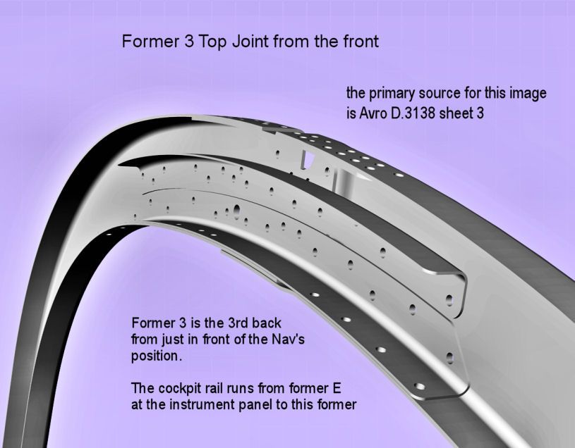
The joint strap has a clear function to bridge the gap caused by the cutout for the top centre stringer, no. 1.
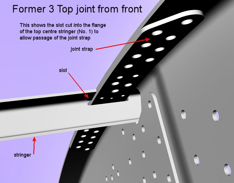
But then the strap has to pass through the stringer. So a slot is cut in the flange of stringer 1.
Would it not have been better to split the stringer and avoid the need both for the cutout in the top of the former and the joint strap? The stringer is weakened by the slot. So splitting it and fixing it to both sides of the former might have been better?
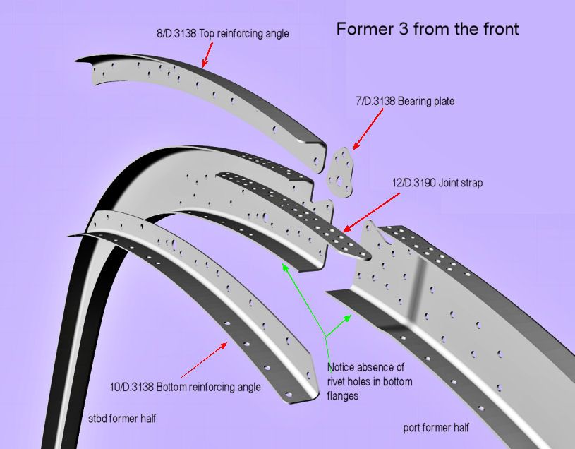
Given the cutouts for threading through the top stringer, the top reinforcing angle has a clear function. But what about the bottom reinforcing angle? I can’t understand why rivets were not used to join the ends of the bottom flanges of the formers. Look at the parts marked with green arrows in the 2nd image. If those parts had been riveted, then there would be no need for the bottom reinforcing angle.
Isn’t it great fun to second-guess the blokes who actually had the responsibility!
Mike
By: MikeHoulder - 30th January 2014 at 10:49
Constructing the profile for Former E
As regards the profile, former E is a cut down version of the standard FCS (Front Centre Section) former. The profile of this was shown in the last two or three posts. The top 25% by height of the standard profile are replaced with a new curve given by coordinates. You can see here.
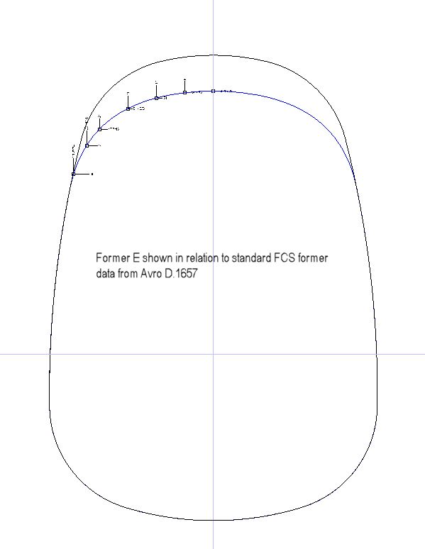
This shows the coordinates that are given in both the Avro drawings D.1657 and D.1916
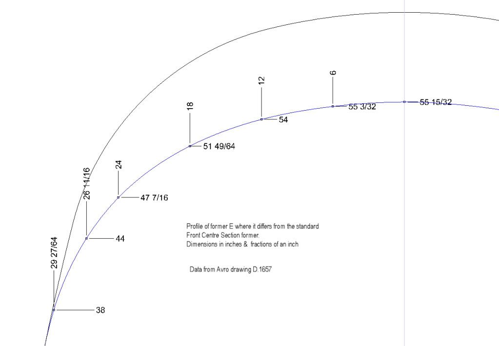
The standard former curve was divided into a large sequence of points, omitting the top 25% by height. A spline mathematical function was used to create the entire profile of former E using these points and those given by the coordinates.
By: MikeHoulder - 25th January 2014 at 09:59
Constructing the standard former profiles from former 1 to former 22. Part 2 of 2.
Here our objective is to find the arc of a circle, radius 216” or 18 feet, which makes a smooth joint with both the two arcs/circles, radius 22.5” on one side of the centre line. The position of the two small arcs/circle is known. The construction method used here is the same as used in part 1, but with a slightly different perspective.
Construction
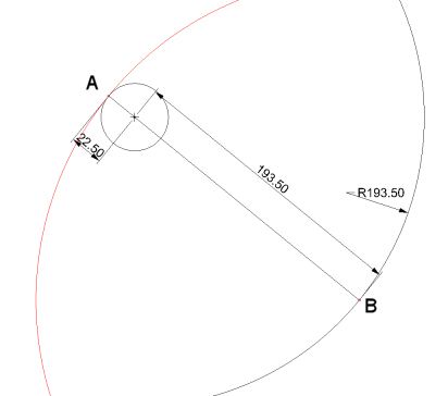
From any point A on perimeter the left half of the top arc/circle, draw a line to the centre of that arc/circle. The centre is known. Extend that straight line a distance of 193.5” to point B. The total length of the straight line is now 216” (193.5 + 22.5 = 216)
The first segment of this line, length 22.5”, is a line from the centre to the perimeter. Hence the tangent at point A is perpendicular to the line AB.
Now if we draw a arc/circle of radius 216” shown in red with centre point B, this will pass through point A. Again for any straight line from the centre of a circle to a point on its perimeter, A in this case, the tangent to the arc/circle of 216” radius at A will be perpendicular to the straight line.
So we have found the centre of a arc/circle of radius 216” whose tangent at point A is the same as the tangent to the small arc/circle at A. Hence we have found the arc/circle, radius 216” and centre the point B which makes a smooth joint at A with the smaller circle.
Now, if we choose another point on the blue curve, call it B’, draw a straight line from B’ to the centre of the small circle and then extend that line to another point on the perimeter of the smaller circle, A’. This line passes through the centre of the small circle so it is perpendicular to the tangent of the small circle at A’. The length of this line A’ to B’ is 216”. If we draw a circle, radius 216” and centre B’, the circle will pass through point A’. Since the line that fixes point A’ is from the centre of the new arc/circle, it too will be perpendicular to the new circle of radius 216” at A’. So both the tangents to the new circle and the small circle at point A’ will be equal. Hence A’ forms a smooth joint between the 216” arc and the 22.5: arc
But we chose point B’ arbitrarily. So any point on the blue curve of radius 193.5” can be the centre of a circle, radius 216” , which forms a smooth joint at a corresponding point with the top small circle.
All this applies equally to the bottom small circle and we have:
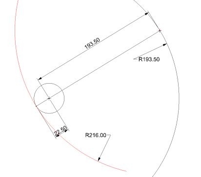
OK, we can find arcs/circles, radius 216”, for both the top and bottom small circles.
But we need it to be the same arc/circle, radius 216” with the same centre. Problem!!!
Easy! If you draw both the blue curves for both top & bottom small circles when those are in the correct position relative to each ,
You will find the blue curves intersect.
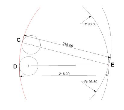
E is on the upper blue curve, radius 193.5”, so an arc, radius 216” centre E forms a smooth joint with the top small circle at point C.
But E is on the lower blue curve also, so an arc, radius 216” centre E forms a smooth joint with the bottom small circle at point D.
So it is the same arc, radius 216”, shown in red that makes smooth joints with both the top & bottom small circles.
Problem solved!
We have, using symmetry about the centre line:
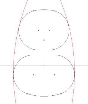
Just chop off the bits of curves that we don’t need and we have produced the standard former profile.
With my CAD system I can derive this with super precision. But in general this is a much more precise way of defining the former profiles than the coordinate based system for the nose section formers.
With compass, ruler & pencil, all these formers can be reproduced on paper by hand to whatever scale is required by adjusting the numbers to suit the scale. In some scales the paper might have to be larger than normal to cope with the large radii 216” & 193.5”.
Next will be the derivation of the profile for former E.
By: MikeHoulder - 23rd January 2014 at 14:30
Yes, Greg, you’re doing fine. Your coords for the 216 radius circle (-181 31/64, -8 7/64) are spot on for the port side side wall. For the stbd it’s (+181 31/64, -8 7/64).
Yes, the X axis shown is the horizontal datum line which is the top of the 3 inch floor. Particularly for Canadian built Lancs, the floor had a depth of 4 inches instead. I have not yet sorted out the implications of that.
The typical precision used by Avro throughout their drawings is 1/64. When it matters, say for a tolerance, they will change to a decimal form of at least 2 decimal places.
Here’s the rub. I’ve implemented the Avro method correctly with a great deal more accuracy than they could have managed at the time.
They give the width of the floor at the datum line as 68.78 inches. I presume, since they go to the 2 decimal place format instead of 68 25/32, that here it matters and no departure from this number will do.
The width at the datum in my drawing is 68.7301. 5/100″ less than stipulated. That’s too much to be ignored.
I don’t think there is any error in my work. I think the difference comes from the difference in drawing technology between then and now.
So, at present, I am trying to find the minimum change in the given numbers which generates a width on the datum of 68.78″.
So far, I think the offsets of the 22.5″ curves have to be increased. For the top, the centre of the 22.5 curve must lie on a line 6.03″ from the centre line (i.e. 6 1/32). Similarly for the bottom, the offset should be 12.03 or 12 1/32.
Mike
By: lanc35 - 23rd January 2014 at 02:31
Hi Mike,
Thanks for this.. I decided to follow along at home 🙂
So I gather from the drawings, the following is known:
Top fuselage radius: 47.5″ @ 0,15.5
Bottom fuselage radius: 63.5″ @ 0,28.5
Side of fuselage radius: 216″
top corner blend radius: 22.5″ offset 6″ of centreline
bottom corner blend radius: 22.5″ offset 12″ of centreline
So, given the same precision you used for the top corner blend having a centre of 39 49/64, is the side wall centre at -181 31/64,-8 7/64 ?
What is the typical precision they go to on the drawing? ie: would they say 49/64 or perhaps as 3/4 if going to 1/16th precision etc?
Presumably the 0,0 coordinate the datum line, does that correspond to the main floor?
regards,
Greg


 Sign In
 February 12, 2011 at 10:27 am