Caribou Main Gear… looking for information.
Ladies and Gents,
I am trying to put together a design for a 1:10 flying scale model of the HDC-4 Caribou and although there is quite a good supply of photos of the type showing the undercarriage on the internet I have not yet come across a schematic of the main gear retract system that would show me how it was done on the original. Neither are there any photos (so far) inside the wheel well that would clue me in on what happens at the forward end of the bracing strut. My problem is that, given the information I have so far, the only way I can make it work geometrically is to assume that the main spar bottom member does not pass straight (ignoring the anhedral to dihedral change) through the nacelle but that the spar takes on the shape of the top of the nacelle to make it the shape of the ‘ohm’ sign.
Does anyone have a drawing or photos that will settle this conundrum for me please?
Robin

By: eye4wings - 22nd January 2013 at 09:08
Thanks again gents!
baj, it must be your aircraft working the display circuit in Australia. I have watched videos of them on YouTube numerous times looking for clues about things like the retraction of gear and how much control throw to give the flap mounted ailerons. (very little is seems – that huge rudder seems to be the key to turning response).
My modelling skills (and tooling) are a severe restriction when it comes to metalwork, but while I can reasonably hope to replicate the slotted flap system at the scale I propose to build the model thanks to the photos that are available on the internet, I have somewhat reluctantly (but with relief having made the decision) decided that I have no chance of replicating the retract system used for the 1:1 aircraft. It is simply beyond what I can reasonably hope to achieve.
And my heavy landing indicator will be the rearward movement of the main wheels, due to the compression of the balsa rear wing spar in the nacelle – and entail a rebuild of the area in all probability!
The outline layout I propose gives a similar overall shortening effect, but as my main aim is to achieve the slow landing speed of the aircraft lightness is paramount… for the whole airframe.
Thank you all once again. Your response and interest is most gratifying.
By: Avro Avian - 22nd January 2013 at 05:48
The aforementioned heavy landing indicator….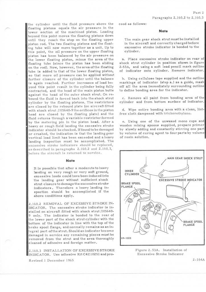
By: Amarok - 21st January 2013 at 15:50
DHC Dash 7 has the same U/C
Hi the DHC Dash 7 had the same U/C, very simple and easy to maintain
you can see some good U/C shots on DHC-4 Caribou Kee Bird II
in this video of the ill fated B29 rescue 🙁
B29 Frozen in Time NOVA
By: eye4wings - 21st January 2013 at 10:29
Haha! … Does that reflect on the Aussie pilot’s sensitivity in the posterior, his macho attitude, or his honesty in reporting Macca?
Or maybe the CO’s opinion on the reliability of any or all of the above?
I now have this vision in mind of the mess full of hobbling pilots with impacted spines shrugging off their injuries with the landing strip littered with bits of angle iron!
By: macca172 - 21st January 2013 at 08:21
Dont forget if its a RAAF Caribou, they had a small piece of angle iron held onto the strut by sealastic, acted as a “heavy landing indicator” Heavy landing, angle iron gone!
By: eye4wings - 21st January 2013 at 08:19
That’s exactly what I was looking for Avian! Thank you for posting it.
My mind was starting to explore that kind of idea for the shortening mechanism, but I had been thinking in terms of the same system as used on the Vickers Viscount and had not yet abandoned the idea of a second hinge in the main leg itself so was struggling with too many floating points!
Unfortunately I still cannot see how I will be able to turn my very restricted engineering (lack of) skills to reproduce the system, particularly as I was hoping to use one of the commercially available 90 degree electric retract units to operate it.
At least the schematic you posted will have directed my thoughts in the right direction but I suspect a lot more tracing paper is going to pass under the pencil before I reach a conclusion.
Scale is a large contributor to the problem as the physical size of the retract units suggest a model somewhat larger – while their abilities to hand out the required torque actually appear to forbid it. Ah well, for once the saying ‘back to the drawing board’ can be used literally!
Thanks to all for your interest and helpful responses – and if I do manage to come up with a promising answer to the conundrum the answer should appear at…. http://www.rcgroups.com/forums/showthread.php?t=1411598&page=8
By: Avro Avian - 21st January 2013 at 03:40
See if this helps…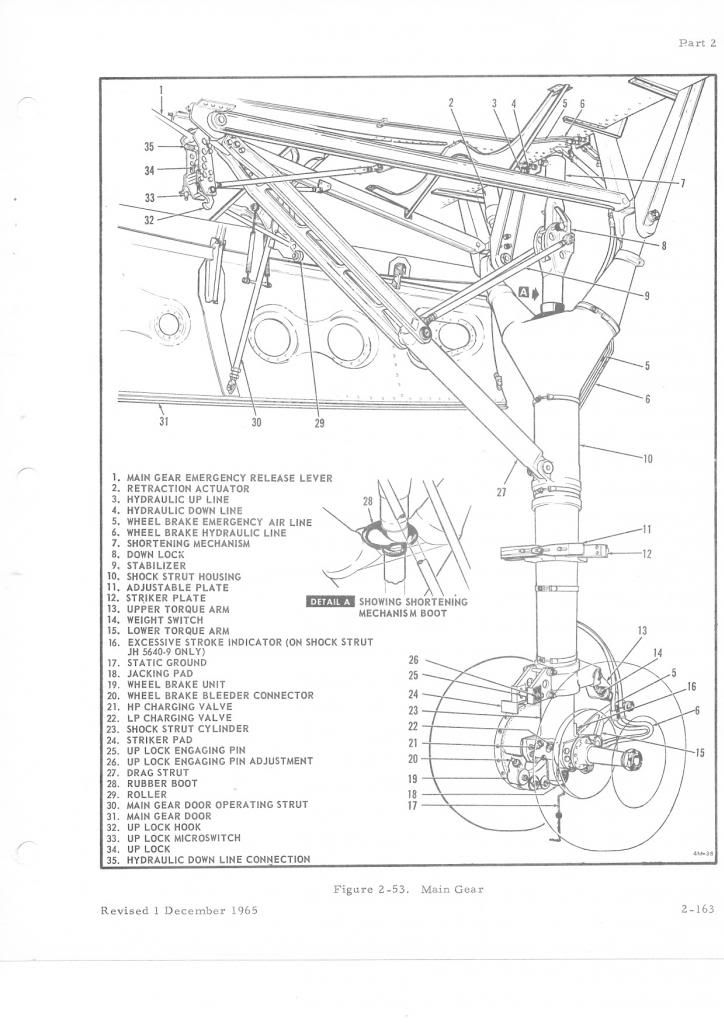
….out of my civvie Caribou Manual.
Note the leg shortening mechanism….
PM me if you would like a clearer image or any other info.:)
By: baj - 21st January 2013 at 02:12
Hi Eyes,
We have two flying Caribou’s here at HARS in Australia.
Contact Bob St John the aircraft co-ordinator. Im sure he help with photos etc.
Good Luck
By: benyboy - 20th January 2013 at 22:33
Sorry, I cant help, but looking forward to seeing the model.
By: eye4wings - 20th January 2013 at 22:17
Thanks Mike.
I don’t see ‘Caribou’ on their exhibit list but I may give them a try.
I am aware that the Queensland Air Museum have taken one of the ex-RAAF aircraft – there are photos on their website. The undercarriage has apparently been replaced with a jury rig.
Before contacting them direct I thought I would try here first as being the sort of place members of different museums might visit regularly.
Using Google search I have been a bit surprised not to see a book coming up so maybe there is not one around to refer to anyway.
Robin
By: Firebex - 20th January 2013 at 20:17
contact the guys at the Malta Aviation Museum there where two of the breed at the fire school at Halfar for a good while not sure if they still exists or not.I know th emuseum was offered one of them at one stage.May be worth a call or email.
Mike E


 Sign In
 January 20, 2013 at 7:08 pm