I am currently looking for documentation or photographs that clearly show the interface between the rear fuselage structure and the front fuselage structure. Photographs taken during a restoration project may be particularly helpful.
I have drawings but the dimensions relating the 2 assemblies are completely illegible.
All help would be gratefully appreciated.

By: airart - 31st March 2025 at 15:29
Try the Malta Aviation Museum.
http://www.maltaaviationmuseum.com/
They’re doing one right now. David Polidano should know the subject inside out.
By: TwinOtter23 - 31st March 2025 at 15:29
You could also try Newark – they have Tiger Moth G-MAZY on their books, which was restored ‘half and half’ [half covered and half uncovered]; as such it would be fairly easy to access, photograph and measure the areas of interest.
Also their Archive might hold pictures from the CARG Archive that covers the ‘build-phase’ of the project. The curatorial contact is given on here! 🙂
By: AgCat - 31st March 2025 at 15:29
Buy a copy of Stephen Slater’s new Haynes manual on the Tiger Moth, if you are serious about your Tiger Moth project, as described on other threads. For example, here:
http://forum.keypublishing.com/showthread.php?t=92924&highlight=Haynes
By: low'n'slow - 31st March 2025 at 15:28
Yes Hugh. I can confirm that some of the information you may need is indeed in the Haynes Manual of the Tiger Moth. Airframe repair and service manuals for the DH82A, as well as parts lists, are also readily available and contain the information you need.
It may also be worth contacting Stuart McKay at the de Havilland Moth Club…
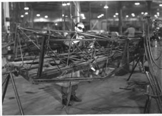
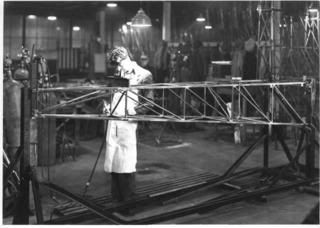
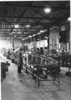
Attached too, pictures used for the Haynes Manual, which might be of help…..
Steve S.
By: low'n'slow - 31st March 2025 at 15:28
Relevant words from Chapter 3 of Haynes Manual. Strongly suggest you buy a copy Hugh, as I have old aeroplane habit that needs funding!! :diablo:
…….
FUSELAGE
The main fuselage frame is constructed in three sections, using various gauges of mainly 7/8″ (22.2 mm) round and 7/8″ square section T45 low-carbon steel tube, which is welded to form individual rigid structures, which are bolted together. The engine mounts, forward fuselage and rear fuselage can therefore be replaced individually to speed repairs.
The core of the airframe is the forward fuselage, to which the engine, centre section struts, lower wing mountings, undercarriage and rear fuselage are bolted. It also makes up the cockpit area, with the wooden floor, seats and ‘control box’ containing the linkages for all the primary aircraft controls, being bolted to the structure.
The two main parts of the forward fuselage are the side frames which when assembled to cross members form the parallel sides of a box structure 7 feet 2 inches (2.18m) long.
The front of each side frame is raked backward to reflect the slope of the non-structural aluminium engine firewall, while the top longerons provide the mounting points for the steel centre-section struts supporting the upper wings.
The two side frames are separated by steel tube cross-members and two 8 mm diameter steel tie rods. These tubes brace the floor, being bolted via flanged end fittings to the lower longerons at the point where the downward tubes coincide, to provide attachment areas for the root ends of the lower wings.
The forward points of the lower side frames also take vertical loads from the undercarriage, act as a mounting for the oil tank and the front of each side frame also bolts to two triangulated square section tubular frames which form the engine mounts at the front of the airframe. The engine mounts extend three feet (0.91m) ahead of the bulkhead on each side of the aeroplane and contain four receptacles for rubber engine mountings, two on each side, which correspond to the cast alloy ‘feet’ attached to the crankcase of the Gipsy Major engine.
The complete forward fuselage ‘cage’ is completed at the front and rear by upper and lower cross members and diagonal bracing, to provide a surprisingly light and rigid unit. To this, a total of 40, 2BA bolts and nuts secure the plywood floor, to which in turn is fixed the control box which forms a central spine at the base of the cockpits, upon which the seats are bolted with the occupants’ feet placed on each side.
The spruce and plywood control box acts as a single mounting point for all the primary flight controls and is removable as a unit for repairs or maintenance. The front and rear control columns are linked by a torque tube and a connecting rod which run the length of the control box, through both cockpits.
For the elevator control, a cross shaft with integral levers immediately behind the rear seat is operated by a short pushrod from the rear control column and is connected directly to the control cables running to the tail of the aircraft. A downward-projecting lever on the torque tube between the two columns operates the aileron cables externally, under the cockpit floor. The rudder controls too, are mounted on the control box and are coupled by connecting rods. The ends of the rear rudder bar extend out of each side of the cockpit and the external control cables run direct to ‘horns’ on each side of the rudder.
The rear section of fuselage is likewise made up of four 7/8″ (22.2 mm) square T45 steel tube longerons which taper through five reinforced bays to a single sternpost at the rear. Built on a jig as a single, rigid, 11-foot (3.35m) welded-up unit, it is designed to be simply bolted in place on the rear of the sideframes and already carries the drillings for the wooden top decking and the mountings for the tail surfaces……
By: HughT - 31st March 2025 at 15:28
Yes Hugh. I can confirm that some of the information you may need is indeed in the Haynes Manual of the Tiger Moth. Airframe repair and service manuals for the DH82A, as well as parts lists, are also readily available and contain the information you need.
It may also be worth contacting Stuart McKay at the de Havilland Moth Club…
Attached too, pictures used for the Haynes Manual, which might be of help…..
Steve S.
Thank you very much indeed Steve – this information is very useful.
I do though have a small issue which I cant seem to resolve – the tie strut between the 2 top longerons at the point of deviation (on the right) actually has a 9 degree chamfer on each end which suggests it is actually offset from the crank and not centred as shown.
By: low'n'slow - 31st March 2025 at 15:26
I suspect that once The Blue Max has battled his way through Northamptonshire snowdrifts, he’s probably the best-equipped person to answer that! 😉
By: The Blue Max - 31st March 2025 at 15:26
Thank you very much indeed Steve – this information is very useful.
I do though have a small issue which I cant seem to resolve – the tie strut between the 2 top longerons at the point of deviation (on the right) actually has a 9 degree chamfer on each end which suggests it is actually offset from the crank and not centred as shown.
Not sure where you mean Hugh?? which tie strut?? Are you talking about where the Front and rear fuselage join? if so there is no tie beteween the upper longerons. Infact there is no tie strut that goes between the top longerons? The front half has a front frame and then a frame at the point it joins with the rear, the rear assembly is a complete welded frame.:confused:
By: HughT - 31st March 2025 at 15:25
Not sure where you mean Hugh?? which tie strut?? Are you talking about where the Front and rear fuselage join? if so there is no tie beteween the upper longerons. Infact there is no tie strut that goes between the top longerons? The front half has a front frame and then a frame at the point it joins with the rear, the rear assembly is a complete welded frame.:confused:
Thank you for your comments.
There is a cross frame member: de Havilland drawing number H27786 located where the bottom (correction) longeron cranks. This item is 10.5 inches long and chamfered 9 degrees at each end.
By: The Blue Max - 31st March 2025 at 15:25
Is this a Round or Square tube?, if you look at the drawings posted by Low and Slow you will see the tubes that are there. There is square tune at the fwd station at the bottom of the firewall, two round tubes with riveted fittings on the ends at the lower wing pick up fittings. These are bolted inplace and the fwd of these two also has two tie rods to the front and rear of it. After that there is the rear frame at the front to rear join. Hope that helps.
By: HughT - 31st March 2025 at 15:25
Its where the longeron cranks on the rear fuselage structure. The Low’n’Slow drawing shows the centre of crank in line with the centre of the cross members – however this cant be the case if the cross members are chamfered across the depth of the material section.
There is also an issue with the dimensions of the rear fuselage that dont match with the part drawings ref DH Drawings H27745 & H27746 – but perhaps we should leave that for another time.
By: The Blue Max - 31st March 2025 at 15:25
The rear section is a complete factory welded asembly, not to sure what point you are trying to make here? The drawings dont match the finished component, nothing new there!!
I can take a picture of that area tomorow on a frame thats in the workshop and post it for you.
By: HughT - 31st March 2025 at 15:24
Thanks that may indeed shed some light on this issue.
The attached sketch shows what I was describing – the cross member; according to the DH part drawings; is chamfered as shown which means that to match with the longeron this cross member needs to be offset from the crank centre or SOP.
By: low'n'slow - 31st March 2025 at 15:21
As Blue Max points out, although the cross tube you mention may carry a DH part number, the rear fuselage frame is officially regarded as a single, factory-jigged, welded structure. Repairs are possible on this, but if the airframe is being restored to fly, they must be carried out in accordance with approved DHSL repair procedures and, in the UK, be carried out by a CAA-approved welder.
A few more images attached. The drawing is from a DH82C parts manual. The welding images from deHMC archive, taken at Nuffield factory circa 1940.
By: HughT - 31st March 2025 at 15:21
As Blue Max points out, although the cross tube you mention may carry a DH part number, the rear fuselage frame is officially regarded as a single, factory-jigged, welded structure. Repairs are possible on this, but if the airframe is being restored to fly, they must be carried out in accordance with approved DHSL repair procedures and, in the UK, be carried out by a CAA-approved welder.
Thank you again for your help.
I should note that I am not interested in building one – I have a background in structural engineering and this is a research project on the structural design and configurations of various aircraft primarily from the 1920s through the war years.
Integral to this is the development of 3d cad models (incidentally 26 years experience in that field) from which I can do geometry analysis, structural analysis and working simulations. To do this correctly I need to be absolutely sure that everything is dimensionally correct.
As I have already discovered a number of dimensional anomalies I cant make any assumptions without some verifiable data. Unfortunately the drawings I have are not that great with some key data illegible or missing.
With regards to the cross member in question – the very shape of the part suggests that it has to be offset from the centre line of the cranked longeron, whereas on some GA drawings; done by others; it is centred – so we have a conflict which requires resolution.
I have also noticed dimensional discrepancies with the rudder spar and the horizontal stabilizer main spar.
This sort of stuff is definitely not easy and consumes many hours just resolving small details and consequently any help in this respect is gratefully received.
By: The Blue Max - 31st March 2025 at 15:18
Hi Hugh
Pic attached, you will see that the cross member is as shown on the drawing.
The 9 degrees tapper you mentioned will be the tapper from the front to rear of that section before the sharp change at the rear.
By: HughT - 31st March 2025 at 15:18
Hi Hugh
Pic attached, you will see that the cross member is as shown on the drawing.
The 9 degrees tapper you mentioned will be the tapper from the front to rear of that section before the sharp change at the rear.
Thank you very much.
Actually the taper from the front to rear of the main section is only 4 degrees, the sharp change or crank is a further 5 degrees to the rear – thus we have 9 degrees.
I thank you again – this warrants further research.
By: HughT - 31st March 2025 at 15:09
[QUOTE=AgCat;1511852]Buy a copy of Stephen Slater’s new Haynes manual on the Tiger Moth, if you are serious about your Tiger Moth project, as described on other threads.
QUOTE]
Thank you for your suggestion – which incidentally I followed through with a purchase of this manual.
I had a look at the details before purchase and noted that the cover states ‘all marks covered’ – unfortunately as it turns out they are not.
The DH82C for example is not covered at all except for a 2 line sentence in the appendix.
The manual is still useful but not as much as I perceived it to be.
By: low'n'slow - 31st March 2025 at 15:08
Also check out pages 32-33!;)
By: HughT - 31st March 2025 at 15:07
Also check out pages 32-33!;)
Yes I saw the ‘chapter’ – just an overview of the differences. It will still prove to be a useful resource, but not what I expected.
Personally I would liked to have seen a more detailed side by side comparison of the variant differences.
My main issue, as mentioned, is the fact that this is supposed to be an ‘owners manual’ for ‘all marks’. So why was ‘all marks’ written on the cover when it barely covers anything else other than the DH82A?


 Sign In
 January 6, 2010 at 12:44 am