Thought to post this nice article here rather then naval avaition .
EA-18 Growler Testing

By: bring_it_on - 23rd March 2017 at 17:46
Next Generation Jammer Increment-2 RFP expected in a few months –
Navy calls for industry participation in Next Gen Jammer technology demo
February 28, 2017 | Lee Hudson The Navy is planning for the second increment of the multibillion-dollar Next Generation Jammer program to enter the acquisition process at the engineering and manufacturing development phase and is asking industry to participate in an upcoming technology demonstration.
The Transmitter Group Technology Demonstration is meant to prove a mature solution exists so the effort can enter the acquisition system at milestone B, according to a Feb. 17 special notice posted on the Federal Business Opportunities website.
“The data collected will support the maturity assessment and provide the evidence to be presented to the Milestone Decision Authority (MDA) in order to receive authorization to release the [request for proposals] for the Inc 2 Engineering and Manufacturing Development (EMD) contract,” the notice reads. “The data to be presented to the MDA will be the cumulative data set from contractor [independent research and development] funded programs, government witnessed testing and government conducted testing.”
Naval Air Systems Command plans to release a request for proposals for the technology demonstration in late fourth quarter of fiscal year 2017 or early first quarter of FY-18. The service will award a contract to up to three vendors with a period of performance spanning 18 to 20 months, according to the notice.
The scope areas for the demo include frequency coverage, effective isotropic radiated power, spatial coverage and spectral purity, the notice says.
Inside the Navy reported in July that the service released a request for information and hosted an industry day for the NGJ.
NGJ is an evolutionary acquisition program providing the service capability in three increments: Increment 1 is mid-band; Increment 2 is low-band; and Increment 3 is high-band. The Navy is set to spend about $3.5 billion on the first increment and about $1.6 billion on the second increment, according to FY-17 Navy budget documents.
“Next Generation Jammer (NGJ) Increment [2] will deliver significantly improved radar and communications jamming capabilities with Open Systems Architecture that supports software and hardware updates to rapidly counter improving threats,” according to Navy budget documents. “Additionally, NGJ Inc 2 will continue across the spectrum of mission defined in the Defense Strategic Guidance to include strike warfare, projecting power despite anti-access/area denial challenges, and counterinsurgency/irregular warfare.”
By: bring_it_on - 21st March 2017 at 20:00
By: stealthflanker - 21st March 2017 at 19:24
im curious how the polarization is selected :3
Perhaps the radiating element is movable, and shaped as “I” slot, thus change of polarization from vertical to horizontal, can be accomplished by rotating the element. Or maybe more solid state solution by patch radiator with 2 ports, one for vertical and other one for horizontal.
By: bring_it_on - 21st March 2017 at 13:57
The US military has suggested that the EMS is a critical warfighting domain [2]. The US Navy has initiated the Electromagnetic Maneuver Warfare (EMW) concept [3]. EMW must be enabled by Advanced Technologies that are capable of RF-agility over a very wide bandwidth, adaptable waveforms, and for many missions high power. Technologies are under development that will provide all the key elements required to enable EMW. The most important technology development is the AESA. An EW AESA is very different from any existing radar or communication AESA. Radar arrays have much lower frequency bandwidth requirements. They usually only need to be single polarization: vertical or horizontal. And do not require 100% transmit duty cycle. The duty cycle reduces the average power output and therefore reduces the prime power and thermal management requirement. Communication systems do require dual polarization; however, the array usually requires less power output. The transmit and receive functions can also be separated into two antennas; one for transmit and one for receive. The wide bandwith and dual polarization requirement of an EW system stresses aperture design as well as the mechanical and thermal density of the T/R module elements. One of the key enabling technologies is the development of the GaN power amplifier for it’s high power and efficiency. The dual polarization is essential because the EW system must match the polarization of whatever system it is encountering. Having dual orthogonal radiating elements enables a system to become polarization selectable.
The other key technology is the receiver/exciter. This is the heart and brains of the system. With the tremendous flexability and adaptability required, the receiver/exciter must be programmable and have enormous throughput. The function of the receiver/exciter is to complement the RF front end with the ability to receive, to process and to transmit any signal of interest (SOI). The receiver/exciter must be capable of processing waveforms for Electronic Support (ES), Electronic Protection (EP), Electronic Attack (EA), & Communications Waveforms. Frequency selection, bandwidth adaptation, detection and demodulation are required. In addition to all the processing capabilities customers usually require that the processor be a Modular Open Scalable Architecture (MOSA).
The IADS mission is just one of many EW missions, but it adequately depicts the rationale for the enhanced technology requirements of EW over traditional radar and communications systems…..
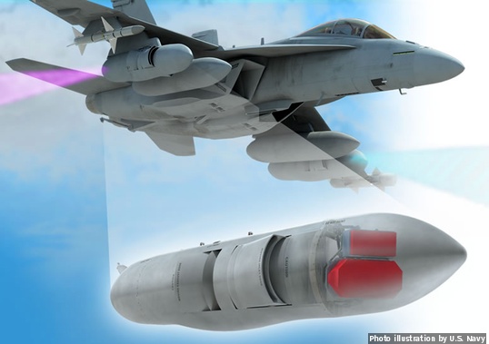
The pod is an aluminum structure with a wideband radome in the front and rear of the pod. Both radomes are identical. The equipment internal to the pod includes the AESA (located in the forward radome), the array power supply (APS, located just behind the AESA), a submerged Ram Air Turban-Generator (RAT-G), a liquid cooling system (LCS), and an instrumentation system. The AESA meets all of the requirements mentioned above for EW missions. This array is uniquely capable of operating full power continuous wave (CW) (100% duty cycle) for transmit. It is also capable of pulsed operation, switching very rapidly between transmit and receive at any duty cycle.
The AESA is very wide band with active transmit-receive (T/R) modules in tile configuration that contain efficient high-power GaN amplifiers in the transmit path, and low-noise amplifiers in the receive path. Both paths contain phase shifters and gain control elements. The wideband array enables the spectrum agility and access needed for Spectrum Maneuver Warfare. The array is mounted on the front of the pod. The dual-polarized aperture elements enable the system polarization to be selectable. The array contains a digital controller that communicates with the MFIRES software defined receiver/exciter unit (SDREU) and sends digital signals to each module setting up the parameters that control the AESA beam (beam pointing angle, polarization, frequency, etc.) [4].
The MFIRES SDREU, shown in Figure 3, is located in the cabin. This configuration was most convenient for the First Flight system. However, future demonstrations would likely locate the MFIRES SDREU in the pod. Both the timing and control and the RF signal are generated in the MFIRES SDREU and sent to the array. The RF system is under the control of the System Director operating one of the system workstations. The System Director workstation receives the navigation (NAV) data; computes the desired beam pointing angle; and sends it to the AESA digital controller directly. The beam steering information is applied to all the AESA modules when the MFIRES SDREU triggers a beam change. The timing and synchronization between the AESA and MFIRES SDREU is very critical; and is a key requirement for the successful operation of the EW RF system – they must operate as one.


 Sign In
 April 6, 2008 at 10:27 am