Grumman F-14A Tomcat
In January 1969 the Grumman Aerospace Corporation was named the winner in a design competition for development of a Navy fighter to fill the role for which the F-111 was rejected. First flight of the new fighter, known as the F-14A Tomcat, took place on December 21, 1970, and the first operational squadrons were deployed on the U.S.S. Enterprise in September 1974. In addition to the previously described combat-air-patrol (CAP) mission, the F-14A was designed to fill several other roles including escort of carrier-launched strike forces, deck-launched interceptions, close-in air-to-air combat, and low-altitude strike missions. These varied missions spelled the need for an aircraft [329] with a combination of high cruise efficiency at subsonic speeds, good maneuverability at high-subsonic/transonic speeds, and a supersonic capability extending to Mach 2.4. Finally, as in all Navy fighter aircraft, low approach speeds compatible with carrier operations were required. As a consequence, it came as no surprise that the F-14A turned out to be an aircraft featuring variable-sweep wings.
Photographs of the F-14A are presented in figures 11.30 and 11.31, and the wing-planform shape is shown in figure 11.32; physical and performance data for the aircraft are contained in table V. As compared with the variable-sweep F-111, the Tomcat has distinct differences in appearance. Among the distinguishing features of the F-14A are the large two-dimensional horizontal-ramp supersonic inlets. In accordance with the Mach number, the angle of the upper ramp, that is, the inside horizontal surface of the upper part of the inlet, varies automatically at supersonic speeds to maintain high inlet pressure recovery. Another identifying feature of the aircraft is the two vertical-tail units necessary for adequate directional stability and control at high angles of attack and high Mach numbers. The crew of the Tomcat is accommodated in a tandem arrangement, in contrast to the side-by-side seating in the F-111.
An examination of the physical data in table V shows that the F-14A is significantly lighter than the F-111 and has a lower wing loading, a higher thrust-to-weight ratio, and a much shorter length. All….
these differences increase carrier compatibility. Two Pratt & Whitney TF30-P-412A afterburning turbofan engines power the F-14A; this is a version of the same engine used in the F-111. Repowering the aircraft with a more modern engine was originally planned; but so far, this has not taken place.
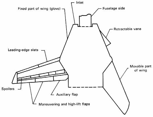
Wing sweepback angle of the Tomcat varies in flight from 20° to 68° to decrease the space required for storage on the aircraft carrier, the wing span is further reduced by increasing the wing sweepback angle to 75°. Wing thickness ratio (in the streamwise direction) varies from 9 percent for the low sweep position to 5 percent for a sweep angle of 68. An important difference in the wing geometry of the F-14 and F-111 is shown in figures 11.28 (F-111A) and 11.32 (F-14A). In terms of the wing semispan in the low sweep position, the pivot of the F- 14A is 10 to 12 percent farther outboard than that of the F-111. According to the paper by Kress in reference 155, the more outboard pivot location results in a much reduced rearward movement of the center of lift with increasing sweep angle. As a consequence, trim drag is reduced and available pitch-control power is increased. The favorable effect of locating the pivot in the proper outboard position is, of course, in accordance with NASA basic research. (See chapter 10.) An interesting feature of the F-14A wing is the retractable vane located on the fixed portion of the wing; the vane is shown in figure 11.32 in both [331] the retracted (low wing-sweep) and extended (high wing-sweep) positions. The function of the vane is to reduce the rearward shift in the center of lift that accompanies an increase in Mach number from subsonic to supersonic values. (See figure 10.15.)
Leading-edge slats and trailing-edge flaps are used to improve maneuverability at high subsonic speeds as well as to increase wing maximum lift coefficient at low speeds. The auxiliary flap shown in figure 11.32 is used only at low speeds to increase maximum lift. In normal operation, the maneuvering flaps, wing-sweep angle, and vane position are automatically controlled by a computer in accordance with a stored program that utilizes inputs from several measured flight parameters such as angle of attack, static and total pressures, and temperature. Manual operation of the wing is also possible. Roll control of the aircraft is provided by a combination of wing spoilers and differential deflection of the horizontal-tail surfaces.
Although available performance information on the F-14A is sketchy, the data in table V show maximum Mach numbers of 2.4 at…


 Sign In
 July 27, 2008 at 5:55 am