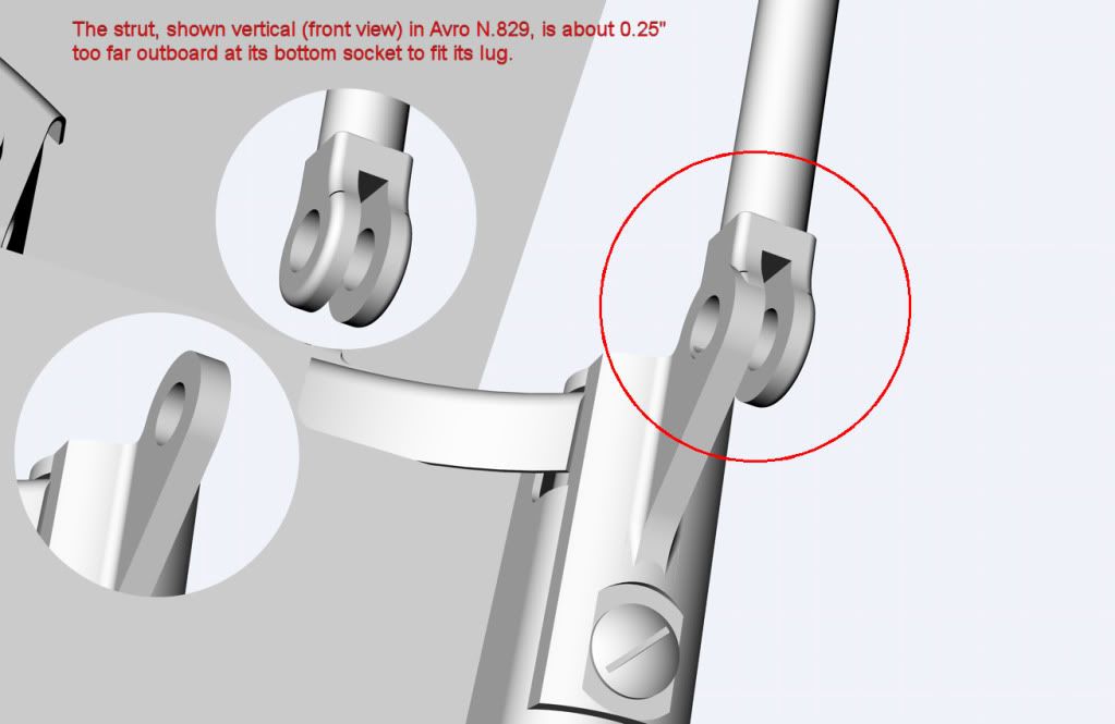
The problem: the forward struts supporting the head armour plate
The strut is too far outboard to engage with the bottom front lug on the seat top plate.
Even with the strut top socket hard against the side of the head armour plate, not allowing for a washer, the bottom strut socket is 3/16″ too far outboard.
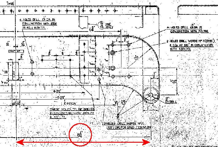
But the centre line of the bottom lug is 8 1/2″ from the C/L of the head armour plate.
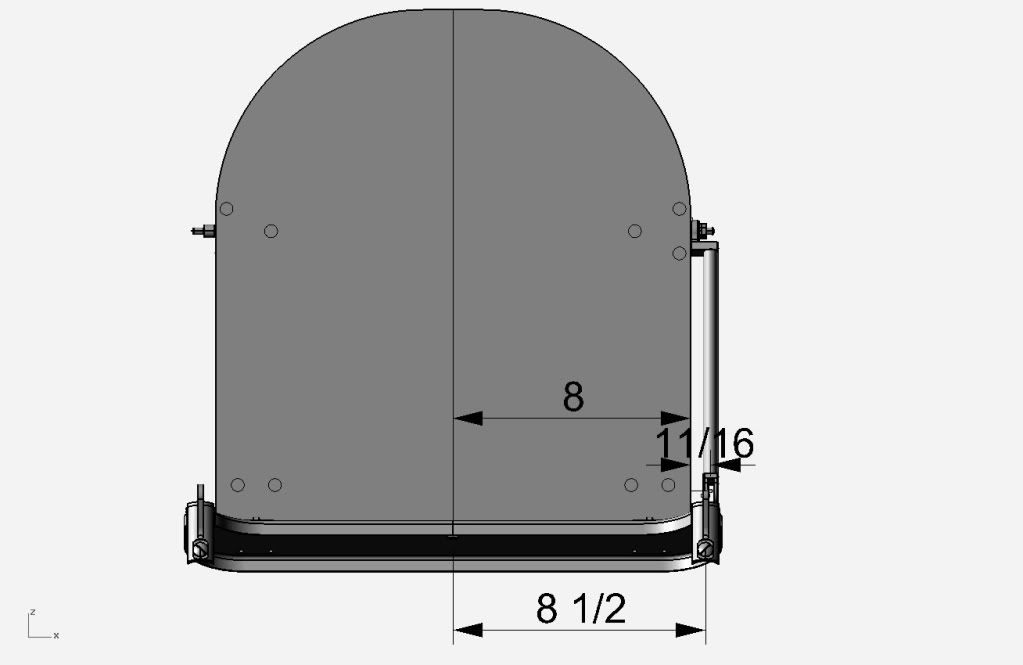
The strut doesn’t engage with the bottom front lug. i.e. 8″ + 11/16″ doesn’t go with 8 1/2″
Here are the justifications of my argument:
The C/L of the front bottom lug is 8 1/2″ from top plate C/L
The width of the top strut socket (lug) from the edge of the head armour plate is 8 11/16″ minimum.
I thought to reduce the width of the head armour plate by 9/32″ each side to allow in addition for a washer each side. But that is not supported by photos.
All this assumes the strut in forward view is vertical. I suppose it could be slanted inwards. But that would be nasty.
Avro drawings used are: 13/N.771 for the seat top plate, 4/N.796 for the strut, & 5/N.796 for the bottom front lug.
Help, please
Mike

By: gillescollaveri - 6th September 2012 at 22:19
Mike,
May I suggest you contact “les ailes anciennes” at le Bourget (air and space museum in Paris) they are restoring the front section of a Lanc that was found in wallis island
You will find their contacts easily on the web.
Rgds
Gilles
By: MikeHoulder - 6th September 2012 at 21:21
A bit of a problem
It seems that PA474 does not have an original head armour plate.
Has anyone got such an original plate in their workshop or storeroom and can do a couple of easy measurements for me?
Just a taster, here is a wire drawing of the work on the front centre section from formers E to 3 with a trial former D port side.
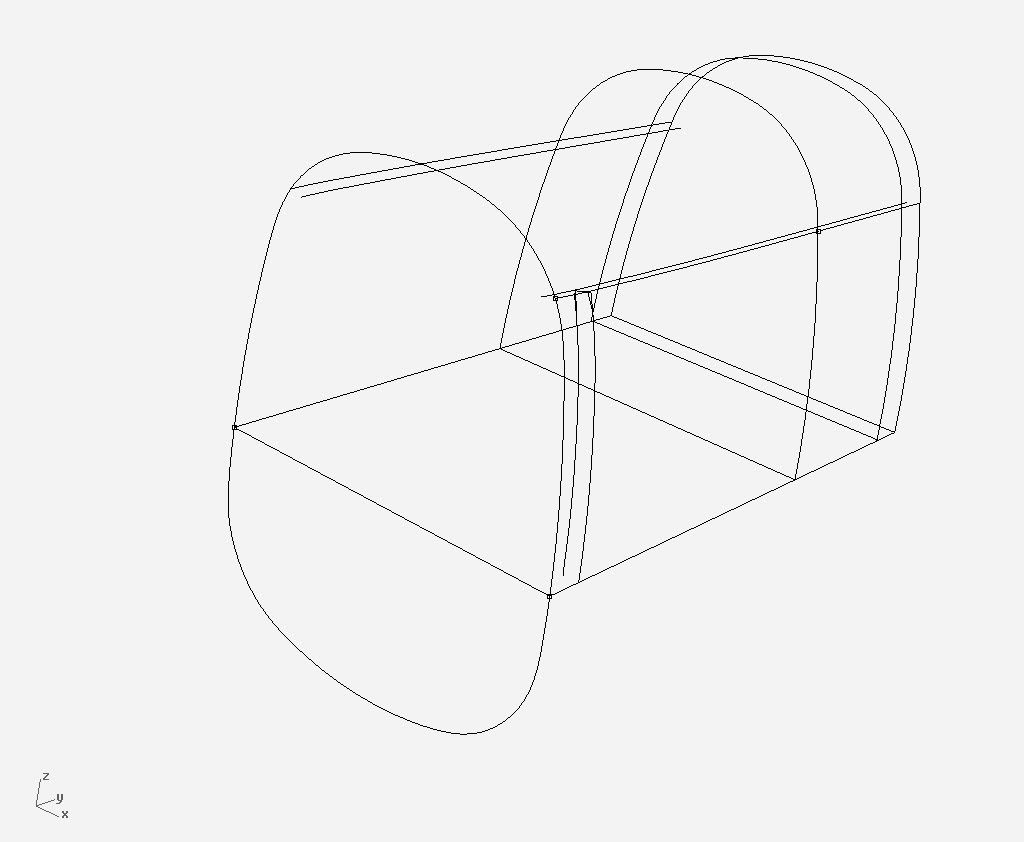
The critical point here is the way the cockpit rail deforms to match the different profiles of formers E and 1. It’s taken me some 18 months to find an authoritative solution from D.3336 etc.
In front view the rails are rotated inwards 14 degrees AND in plan view curved inwards towards the front by just under 1 1/2″.
Mike
By: MrBlueSky - 27th August 2012 at 23:28
Mike, go straight for the jugular contact the BBMF…
http://www.raf.mod.uk/bbmf/contacts.cfm
or try any of these…
http://en.wikipedia.org/wiki/List_of_surviving_Avro_Lancasters#United_Kingdom
One I’m sure will help, its what I do and it works most of the time…;)
By: AndyG - 27th August 2012 at 22:06
Stuart, I’m going to ask Tim to do that. But if anyone else has a chance to check for me, please. There are some disadvantages living in Argentina!
Mike
Hi Mike,
Is the seat and armour common to the Lincoln?
By: MikeHoulder - 27th August 2012 at 14:15
Stuart, I’m going to ask Tim to do that. But if anyone else has a chance to check for me, please. There are some disadvantages living in Argentina!
The critical things to check are the three dimensions:
1. the width of the head armour plate. Is it 16″ or is it 15 5/8″?
2. the distance between the strut tube centres at the top. Is this 17.475″?
3. the distance between the strut tube centres at the bottom. Is this 17″?
If these dimensions are respectively 16″, 17.475″ & 17″, then an eyeball description of the strut. Is it vertical in front view? & if so how on earth can it be so with these dims? If it’s not vertical, where is the bending or easing which allows the sockets to fit onto the lugs?
If those dimensions are not these, how do the struts, sockets & lugs differ from my drawing?
Don’ forget about the top lug behind the armour plate. In the configuration shown in the Avro drawing, the body of the lug must line up with the edge of the armour plate. It can’t be inset. Otherwise the top socket of the strut would foul the armour plate.
Stop now, Houlder. Stop! Or someone, ship me by Fedex a whole Lancaster. Better two of them so I can see how the changes went.:D
Mike
By: MrBlueSky - 27th August 2012 at 13:28
Mike have you not had a look at one of the seat’s that still exist to solve this little problem?
By: QldSpitty - 27th August 2012 at 10:25
I,m thinking a drawing error on the plans..
By: MrBlueSky - 26th August 2012 at 22:55
Hi Mike…
Can’t help you I’m afraid, but can sympathize with the inconsistencies in the drawings.
Matt our CGI/CAD guru has started to come across this himself with the virtual Whirlwind.
Your lucky to have some drawings to work with as we have none apart from a single GA drawing of the pilots seat and a couple very poor quality, parcial view’s from the Pilots Notes… 🙁
Excellent work Mike…
Stuart
Whirlwind Fighter Project
By: MikeHoulder - 25th August 2012 at 21:03
A deeper analysis of the problem
This is a problem of an inconsistent geometry with the forward support struts to the head armour plate on the pilot’s seat of the Lancaster. It is beginning to look to be an interesting problem and is worth a closer examination. I am not an engineer myself. I just like drawing and, of course, the Lanc. But I always invite Geoff to go through my work and rely on his guidance and comments.
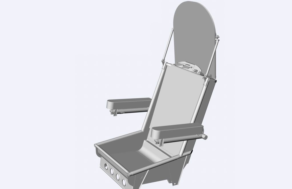
Here is the pilot’s seat I have drawn. It is very nearly complete. All individual components have been drawn using Avro source material. Each component is in fact a separate drawing and, relatively easily, can be projected onto the standard 2D views with its dimensions. I have omitted rivet holes as they, particularly, are very expensive in computer memory requirements. They can be added for individual components at a later stage if required. As regards the seat, I have omitted also the Bowden cable connecting the harness release control to the harness release itself. I have not the skill to draw such a cable in a natural form. A couple of other non-visible items are omitted such as the harness release pin itself and the long harness release spring enclosed within the spring tube. I have taken liberties with various nuts & bolts.
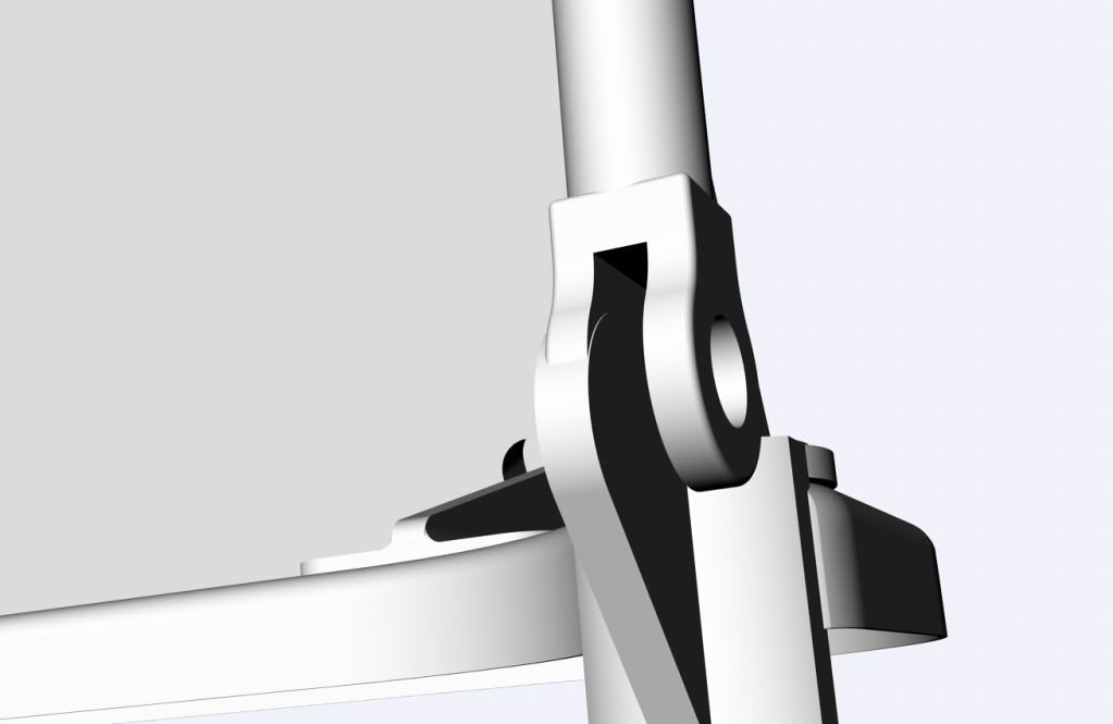
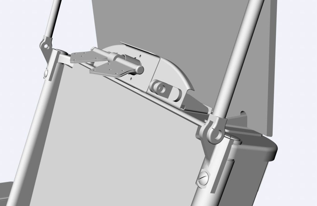
Here is a closer view of the problem area. It shows the top area of the seat with the central harness release and the elevator gust locking bar socket. At the sides are the forward bottom lugs to hold the bottom ends of the strut sockets. Above is the head armour plate with its support struts.
Here is the problem itself. The location of the top parts of the support struts are inconsistent with the location of the bottom parts of those struts. The struts are shown vertical in front view in Avro N.829. But then the sockets at the bottom of the struts do not engage with the corresponding lug on the seat top plate.
Here are measurements of my drawing of these items. The top dimension has been rounded down 1/64” by the system and should read 17 3/8”, not 17 23/64”. It’s that 3/8” that is the problem.
Taking dimensions directly from Avro drawings, we have 17″ between bottom strut centre lines and 16 + 2*(11/16) + 2*(0.05) = 17.475 ” between top strut centre lines.
The sources for my measurements are:
The 17″ comes directly from 13/N.771 (dist between horn centres of seat top plate)
The 16″ comes directly from 2/N.796 (width of head armour plate)
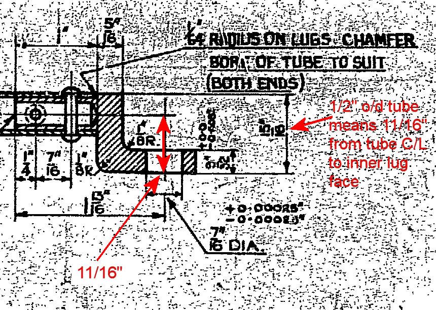
11/16″ is a simple calculation from 4/N.796 (tube C/L to inner face of top socket, 15/16 – half tube width)
0.05 comes directly from 18/N.796 (special washer between inner face of strut top socket and edge of head armour plate/top lug)
This demonstrates as much as I am capable that the inconsistency is a real anomaly of the Avro engineering drawings.
Ok, so what to about this. Three possibilities.
Here are some critical dimensions of the strut comprising a tube, two forged sockets either end of the tube and the two lugs to mate with the sockets.
Force the struts into the correct locations and orientation: This requires sufficient play in sockets & tube to make an adjustment of a double bend, width approximately 1/4”. The socket & lug forgings are solid and tightly specified with given tolerances. No play there. The tube, 8 9/32” in length, is of stainless steel with an outside diameter of 0.5” and a wall thickness of 17G (0.0562”). Any fitting of these support struts in service is clearly intended to be by hand. Geoff’s comment here is “no way can a mere mortal bend that tube with finger pressure….”. So this possibility fails.
Easing the mounting holes: Geoff reminded me of the mostly humorous tension between the Drawing Office and the Production Dept. Easing was the first call when things did not fit as so often occurred. Of course, these days with 3D CAD such tension no longer exists:). Well aware of some of the deficiencies of engineering drawings and the need for such adjustments, I’m not sure if they will be adequate in this case. In 4/N.796 the socket bolt holes of the strut are given with tolerances for the lower socket 3/8 +/- 0.00025” and for the upper 7/16 +/- 0.00025”. The mouth of the bottom strut socket is given +0.005”/-0.000”. Easing to get the strut to fit fully with its upper and lower lugs needs an angle off the vertical of greater than 1.22 degrees. This angle requires easing of a size much greater than these tolerances. So in the abstract garden of my CAD, it looks as though easing itself cannot do the job.
Inconsistent versions of the Avro drawings: When I looked at the last amendment date on the various drawings, there seemed to be a real possibility that the problem at least was here. Here are the drawings and for each up to their last three amendment dates:
N.829, G.A. of armour & seat , 15-6-42, 4-1-43,10-6-44
13/N.771, Seat top plate, 27-7-42, 20-5-49, 8-11-49
2/N.796, Head armour plate, 6-8-40, 4-5-44, 23-1-46
4/N.796, Strut, 11-5-42, 18-10-43, 18-1-44
5/N.796, Bottom lug – forging, 7-10-43
5/N.796, Bottom lug, 12-5-39, 23-11-49
7/N.796, Top lug – forging, 5-10-43
7/N.796, Top lug, 16-5-39, 15-8-49 (illegible)
5/N.796 & 7/N.796, the top & bottom lugs both last modified in 1949 look to be good candidates for inconsistency. But they both use the original forging drawings issued in 1943. I believe the only changes can have been the depth of machining the forgings (about 1/16”) and the tolerances.
Probably the most interesting amendments were those to the head armour plate between 1940, 1944 & 1946.
Does anyone know what changes were made to the head armour plate between these years?
Mike


 Sign In
 August 20, 2012 at 9:04 pm