Good and Bad!
I’ve been trying to solve my problem of the most uncomfortable gap in my drawing between the top of frame K and the nose longeron. The turret deck and longeron are slanted upwards to the front. I had thought the longeron formed a straight line from frame E up to frame K.
Looking at photos of the restoration of FM104 which show the rivet lines of the longeron very clearly, it seems that the longeron in the first section from frame E to frame F is horizontal, not slanted. It begins the upward slant at frame F with a kink.
Here is a photo of FM104 which suggests this:
Here is a much better photo by Den Pascoe showing the kink. The photo is subject to the stringent Airliners usage rules. So, please, right-click on the icon here and choose option ‘open image in new tab’ or new window.
I’m sorry about this; but I don’t know of a better way (anyone?).
But if the slant starts at frame F, that will go a long way to solving my gap problem. Do people agree that this kink exists?
That’s the good. Now, the bad. Could there possibly be an error in Avro drawing D 2310 for frame H? I make the datum line in this drawing to be 18 mm (0.71 ins) too low in relation to the rest of the drawing. I’ve wracked my brains to find an alternative explanation – distortion, my calculation error etc. But I can’t.
The drawing was used to build only 7000+ Lancs. So how can the drawing have an error? Has anyone else found errors in the Avro drawings?
In this case, 0.71″ is important as it causes the slant angle to be exaggerated which in turn creates the dreaded gap at the nose.
Mike

By: Peter - 20th February 2011 at 15:21
Whoopsie MIke, that is PA474 with BBMF Coningsby England, you can tell as she is currently the only flying Lanc with Rebecca antennas fitted.
By: JT442 - 20th February 2011 at 15:15
Thats not Canada…. I was involved in the major of PA474 at Coventry a few years back. Most of the technical pics used in the forum thread were mine…
By: MikeHoulder - 20th February 2011 at 15:11
That’s great. The dreaded gap at the nose was giving me a lot of grief. I’ll redraw the nose section and send you a copy.
The only things I can suggest for the headache:
1. A pint of Tetleys (I owe you that). You being in Canada, it’ll have to be a virtual pint.
2. My horse Tornado lives underneath my study. So I would go for a cross-country blast on him. But that might have to be virtual as well.
Mike
By: JT442 - 20th February 2011 at 15:01
Try this
By: JT442 - 20th February 2011 at 14:43
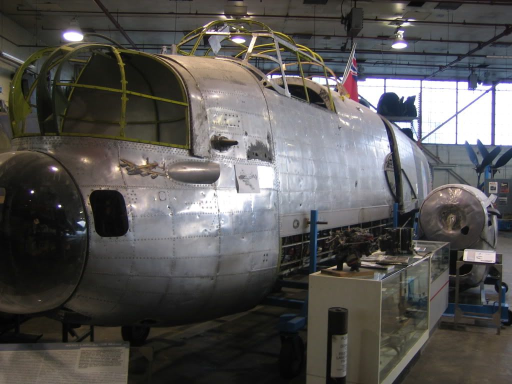
I don’t know the frame numbers, so bare with my descriptions. In my 2nd photo, it appears that the longeron in question is slightly angled up starting a the transport joint, but there is a kink starting between the first and second frames fwd of the transport joint which incrases its angle significantly (+3 or 4 degrees). The kink in the longeron would not be at the frame joint from a structural ridgidity point of view, hence it appears to be some 3 inches aft of the 2nd frame.
I have a headache now…..:rolleyes:
Actualy, it looks as if there are two kinks -each located at the frame joints in this pic….. deduced by the highly technical approach of holding a rule agianst the rivet lines on the screen……
By: MikeHoulder - 20th February 2011 at 14:36
Lancaster nose longeron kink
Yes, JT442. The 2nd photo illustrates it very well. Super photos by the way.
But in your photo it seems more of a curve rather than a kink with the apex of the curve well in front of frame F, almost at frame G.
Your photo is square on. So there is no distortion. It looks to me that your photo proves the kink/curve in the longeron. Agreed?
Many thanks
Mike
By: JT442 - 20th February 2011 at 14:18
Perhaps a better view would help. I’m assuming you’re talking about the longeron which forms the bottom of the turret and runs to the nose transport joint.


 Sign In
 February 20, 2011 at 2:13 pm