Hi everyone.
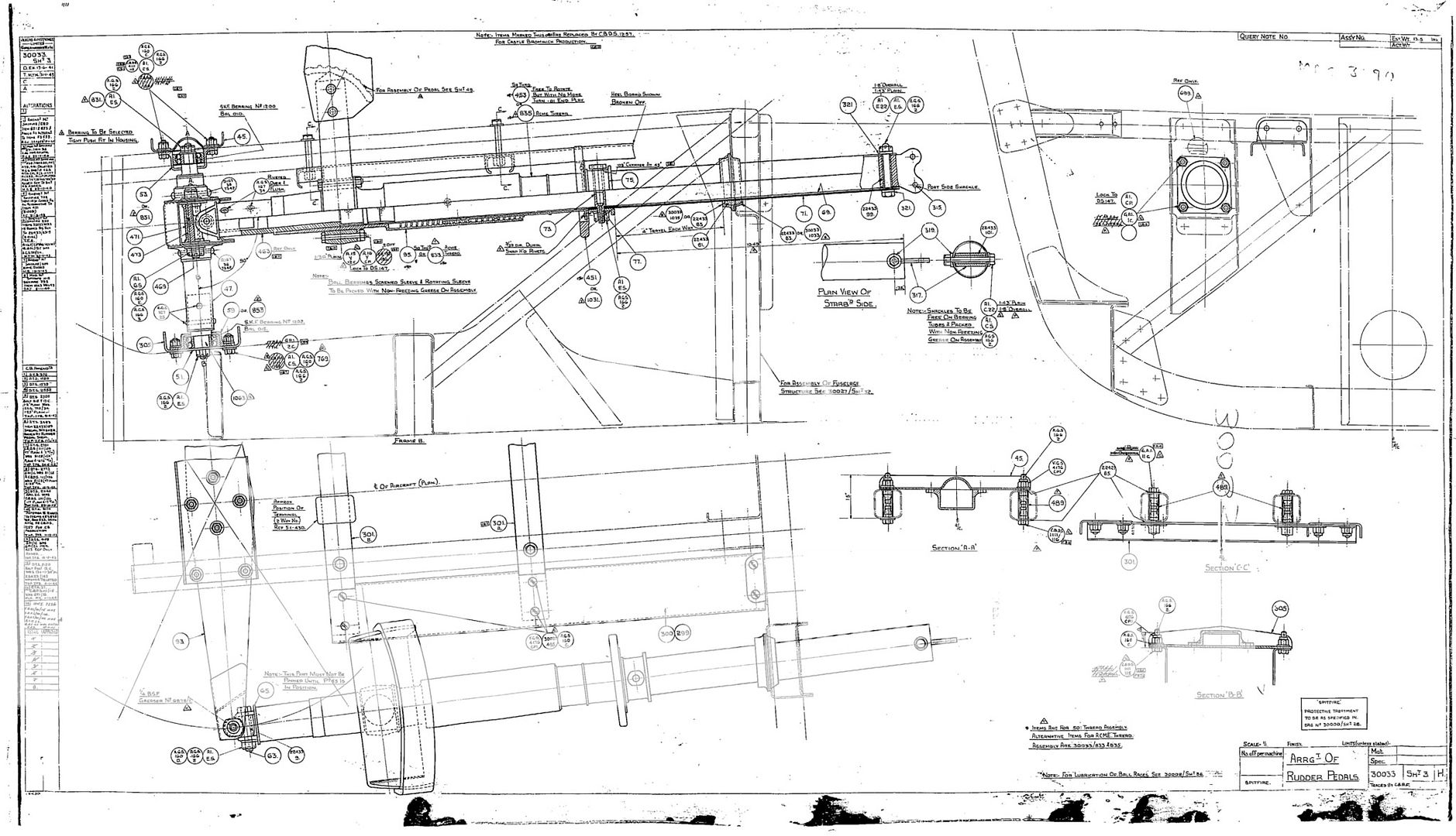
Could anyone tell me how, on a spitfire rudder pedal arrangement, the pedals are kept in the upright position? I have drawing 30033 sht. 3 but I cannot make out what prevents the pedals from swinging left to right! I must be not seeing something!! Can anyone help please.
Many thanks for any info.

By: cornovii - 28th May 2014 at 21:58
Bruce.Thank you very much for all your input on this subject. It really is much appreciated. For now, it will just have to remain a mystery.
Rocketeer may be the person with the answers as he just might have one in bits by now!
Regards
Ken
By: Bruce - 28th May 2014 at 21:32
OK, point taken – the end two would presumably be to secure the square section onto the tube then. The other one, I have no memory of!
I seem to recall that the square section was sweated on (ie with solder) and pinned.
By: cornovii - 28th May 2014 at 17:07
Hi Bruce.
It’s not clear at all. I do have a copy of the Swedish parts book and nothing is shown for these items!
The only reason I can come up with for that is that the list is for a later MK. And maybe things changed!!
But, if you look at the photo Rocketeer posted in response to my question, he has laid the inner and outer tube side by side and you can clearly see on the inner tube the hole for the cable attachment, then the hole for the pin in item 75, next you can see the hole about half way where the threaded adjuster would be and then one further hole towards the end where the rudder pedal would be fitted. There should be another hole but I can’t see it in photo. None of these are shown in the Swedish list but they clearly exist.
I hope Rocketeer will be able to offer some advise. It’s all a mystery to me!!
Or maybe Ian_ could investigate further the rather bent one he has! But I guess it would take some straightening out 🙂
Thanks again
By: Bruce - 28th May 2014 at 16:36
Its not the clearest of drawings is it!
There are no fasteners in each of those three positions. Nothing at all.
Have you got a copy of the Swedish parts book?
Bruce
By: cornovii - 28th May 2014 at 16:19
Hi Bruce.
No, I’m ok with the pin that secures item 75.
If you look further along the tube, towards the rudder pedal, when you get about half way along the threaded part, item 95 sq thread or 833 acme thread, there seems to be a pin that is un annotated. I’m quite sure this to stop item 453, sq thread or 835, acme moving down the shaft? If you move further down to the rudder pedal, there are two more pins about 1 1/4″ apart that are un annotated. These are the two I have the problem with!! Further down toward the rudder bar are the two other pins that you have mentioned AGS 167 34 riveted over and flush. I am ok with these. It’s the two right by where the rudder pedals are bolted on that is causing me to bother you guys. I need to fully understand how it all works before I can start to make anything!!! I know I’m not very good at explaining things so please stick with me!
Thank you very much for your input
Ken
By: Bruce - 28th May 2014 at 13:20
Do you mean the pin securing Item 75 on the above drawing?
That one secures the aluminium collar which the adjuster bears down on.
The two pins close to where the pedals attach are annotated AGS107, if they are the ones you are talking about? They are taper pins which hold the end fitting into the square tube.
Bruce
By: cornovii - 28th May 2014 at 13:10
TonyT
Thanks for the links. Very interesting but unfortunately I don’t think they help with a answer.
In Rocketeers photo you can see some witness marks of a collar pinned to the inner tube where the threaded part is. I think this prevents the inner thread turning down the outer thread. The drawing you posted shows two more pins close to where the pedals attach. On Rocketeers photo you can only see one pin hole and no witness marks of any collar! This is the part I am having a problem understanding the job the pins are doing? I think they must pin collars to the inner tube but for what purpose?
Rocketeer is restoring his rudder bars at the moment so I am hoping he will be able to throw some light on to what is happening with these pins.
Again, thanks very much for your help and input.
By: TonyT - 28th May 2014 at 10:00
Not sure, do the other images here help? I would imagine the adjuster one attaches it to the shaft, and looking at the image below, do the two near the pedal attach that to the other shaft too?
http://forum.keypublishing.com/showthread.php?103571-Spitty-Rudderbar-slides
http://i536.photobucket.com/albums/ff321/taylortony/Spitfire%20MKx1x/Cockpit19.jpg
http://i536.photobucket.com/albums/ff321/taylortony/Spitfire%20MKx1x/Cockpit21.jpg
By: cornovii - 28th May 2014 at 01:23
TonyT
Thank you very much for drawing.
I see on drawing there are 3 un identified pins, 2 near where the pedal is attached and 1 in the centre of threaded pedal adjuster! Is there any chance you can tell me what it is these pins do?
Many thanks
By: TonyT - 26th May 2014 at 16:59
By: cornovii - 7th May 2014 at 23:23
Tony.
Yes, thank you Tony, I see it now. You have some work on there but I’m sure you can do it!!
By: Rocketeer - 7th May 2014 at 22:38
that is shown in the second pic
By: cornovii - 7th May 2014 at 22:36
Tony.
That’s good photos thank you. Can you see if the tube the pedal bolts to has got a squared piece in the end? If it has then it would be as Bruce has suggested.
Many thanks
By: QldSpitty - 7th May 2014 at 22:31
Here’s a bent one but it gives an idea. A complicated bit of engineering.
Lovely MkI pedal Ian..You lucky b@st@rd 🙂
By: Rocketeer - 7th May 2014 at 22:20
Here are a couple of pix – showing the square bit….restoration will be….err….interesting!
By: cornovii - 7th May 2014 at 17:16
Ian
Thanks for the pics. Yes. You are right, it looks complicated. Looks as if it will be a challenge but we wouldn’t want things to be too easy……would we!!!
Regards
Ken
By: ian_ - 7th May 2014 at 16:46
Here’s a bent one but it gives an idea. A complicated bit of engineering.
By: cornovii - 7th May 2014 at 14:12
Bruce.
Thank you Bruce. I’m going to make a set! Just having the tube that passes through spherical bearing turned and ground to size. Couldn’t do that myself. I don’t have a grinder.
Ken
By: Bruce - 7th May 2014 at 14:06
Yes, quite right. Internal square section at the forward end, scroll thread for pedal length adjustment at the other.
I wouldn’t want to make one!
Bruce
By: cornovii - 7th May 2014 at 14:01
QldSpitty
I am thinking lower down where the pedal is bolted to the tube. What stops the tube rotating?
Rocketeer.
Understood Tony but what stops the tube rotating? There must be something internal. But what and where!


 Sign In
 May 6, 2014 at 12:41 pm