Hello;
This is a somewhat different topic than my last question, so it hopefully warrants it’s own discussion thread.
I have done my second experiment in metal forming to see if I have the skill to make 2024-T3 fuselage frames for a replica Spitfire. I wonder if 2014 is as formable, since frames are often built with this alloy. I’ve never done hammer forming before, so my first sample came out awful. I did a little more thinking/studying, and, with the help of an Australian website (thanks Ross E.) my second one came out so much better, that I now believe I could make fuselage frames. The only remaining mystery is straightening the slightly backward-curved web of each frame, which happens when I hammer bend the outer and inner flanges 90 degrees. I have to find a stretcher/shrinker and get some practice on it. To make the fuselage frames, I am using the “alloy-sandwiched-between-the-two-wood-plates-and-hammer-a-lot” approach. If you’ve ever done this or seen it, what I just said will make perfect sense. If not, I’ll clarify again if needed, possibly with pictures.
I thought I would set up the early work on a Spitfire replica (all metal) as a series of challenges to be met and overcome. I now feel that fuselage frames are do-able. There remain several big hurdles. Let me list a few of them:
1. Wing Spars. Steve Vizard, Airframe Assemblies Inc. UK, has original square tubes, bent in a press for the full scale Spit, and I think his company is the only one on earth doing this, are they not?
Question: Is there a reasonable alternative, using metal, to make Spitfire wing spars other than bent tubes? Some kind of web with rivetted-on flanges? A metal box spar??? Any thoughts on a possible design and/or alloy to be used for this?
What does the Stewart P-51 use for spars? I know there are 2 spars on a Mustang, but I’m not even familiar with how they’re made on the P-51. If they’re strong, could some similar construction be adopted for use on a replica Spit?
2. Leading edge wing skins. This is a tough one. They were stretched over hard wood and metal dies using a monster press for the original. Vizard’s company wheels them to get the same results. Again, any thoughts on making them? Would it be acceptable to use several pieces from root to tip? or at least separate skin pieces near the root, where the bend is located? What alloy would make good leading edge skins?
3. Longerons. These have their own challenges, but are probably more solvable then the previous two items. What alloy is best? You can buy hat section 7075-T62 Clad QQA 250 in the USA, so if you could find a suitable shape and thickness, would this suffice for datum and backbone longerons? For the datun longeron, you could add a doubler near frame 5, going back a few frames, just like the original.
Well, that’s enough for now. I was pretty happy when I managed to bang out a decent looking fuselage frame sample yesterday, but I realize that doesn’t make an airplane. Baby steps. This will only take 4 lifetimes.
Thanks, and please chime in. I could use the help and that’s the beauty of forums.
Cheers again from Ottawa, 2 seasons, winter and construction. Tom.

By: Tom Kay - 4th September 2007 at 23:35
Hey D;
Thanks for digging. Sometimes when you get to the details, it’s not quite what you thought. But appreciated anyway.
Tom.
By: DazDaMan - 4th September 2007 at 22:02
Off the top of my head, I couldn’t recall exactly, other than that the aircraft is sadly no more due to some kind of engine failure.
From further “digging”, I found it was, unfortunately for the means of your project, an all-wooden design based on the Jurca MJ10, built to 75% scale as a low-back MkXIV. The website doesn’t provide any engine details, nor any dual-control capability (not likely, but not impossible, I guess), but definitely a two-seater.
(pic via www.marcel-jurca.com)
By: Tom Kay - 4th September 2007 at 21:53
DazDaMan;
Thanks, but how about some more detail.
Who did it? Is there a kit? What scale is it? Is it all metal? Are you also talking about the Aussie Mk26? Is the 2 seater a bubble canopy like the pics I provided, or a highback with someone stuffed in the back ? Is it dual control? Etc.
Please be effusive.
Tom.
By: DazDaMan - 4th September 2007 at 21:45
It’s been done….
By: Tom Kay - 4th September 2007 at 18:56
Why Not Make the Replica Spit a Two Seater?
Hello;
Bless me father, for it’s been a while since my last post…
One thing that has been bothering me about the whole concept of building a Spitfire replica, is that it’s a very solitary project. It’s a single place aircraft, and despite the expense and years of work, can ultimately be enjoyed by only one person.
I recall that one of the things I enjoyed most about flying years ago, is having someone with me. I didn’t happen often, other than instructors, but I did like the idea of sharing the experience. So a Mk IX Spit seems wrong, purely from that perspective.
I have been studying the Mustang a bit lately, and at first that seemed like a good alternative. Merlin powered, beautiful lines and certainly a significant place in history. Probably easier to make with its straighter skins, and easier to ground handle with its wider track. There seems to room for the second person in the Stewart and other Mustang replicas, although the Stewart is no longer in production, including the plans from what I have heard. However…
The Spitfire is not an easy aircraft to leave. So I have considered making the Spit a two seater, sort of like the Aussie Mk26, but definitely not like the trainer. I find the trainer two-seater to be unattractive at best. That bulbous extra canopy really detracts from the looks, in my opinion, no offense intended to Mrs. Grace and others who own them. So is there a way of making a two-seater, possibly even a dual control Spit and maintaining the general look ?
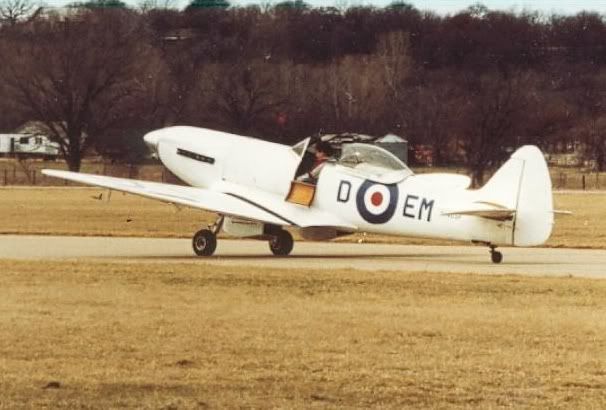
First, I’d have to give up the MkIX highback look. I prefer the highback, but I could live with a lowback, like the P-51D, with it’s teardrop canopy. So it would effectively be MkIX or MkXVI lowback.
If you’re so inclined, please have a look at the 2 pics below. The first is unaltered, and the second has the canopy stretched. It has to move forward 5 or 6 inches, and back about the same amount, maybe more. Does it look odd? Does it look terribly oversized? Not as odd as the trainer two-seater. And with a 70 % replica, the pilot’s head would be pretty close to the proportion shown in picture 2. Could we squeeze a second person behind the pilot? I’ll have to do some sketching and find out. Frame 11 would have to change at the top, so the rear seater could climb over it, but we shouldn’t need armour plating today.
Wadda ya think? After all the expense of building a Spit replica, it would be nice to share the flying experience. Observations, ideas? Is the concept feasible?
Cheers, Tom.
By: Tom Kay - 24th August 2007 at 02:08
AVI;
Thanks for your input. I’ll respond to various points.
I have used the term “design” to describe what I am doing with the spar, but at this point it’s more like coming up with a concept. A design would involve calc’s and I’m not able to do that without help. I hear your point about the wing as a whole, but my initial focus is on the spar concept. Simply finding a way to do something close to Mitchell’s spar. A general layout of parts and shapes and how it goes together to form a spar. Then a D-cell.
I am fairly familiar with the structure of the Spitfire, although no expert. I have enough original drawings to know that this would be very hard to do. I have no intention of becoming an expert right down to the last rivet, even if that is a good idea, because it would take too long. I intend to mimic as much as I can and simplify where possible, such as sheet metal wing ribs instead of truss-type ribs, if that seems strong and workable enough. The Aussie Spit uses that approach for its ribs, as do many homebuilts.
My project, if it ever commences, will be a MkIX. Four blades, clockwise rotation from the pilot’s point of view, no Griffon bumps.
Although I may have to increase the area of the H-Stab, every effort will be made to keep the wing a scaled, proportional size. I will do an estimate at some point of total weight, and wing loading to see if this seems feasible.
The spitfire wing does have a rear spar, but it’s almost just an attach point. I have recently heard that Spits have flown without without the rear spar bolts in place (an obvious oversight) and that apart from some upper skin buckling, everything worked out fine. I would approach my scaled concept in the same way, most of the strength in the front spar and D-cell.
I think that about covers what I wanted to respond to.
Tom.
By: RF769 - 23rd August 2007 at 21:53
Wouldn’t it be cheaper to buy a used Lambo like an older Countach?
Not in Norway… You can get a banger Countach with lots of work needing to be done for about £ 60-65.000….
By: AVI - 23rd August 2007 at 21:19
Wings
OK, Tom, here I go again. Why don’t you check out some homebuilt websites such as the KR2 and the Thorpe? You might also want to examine the Spitfire wing as a whole assembly instead of placing your entire focus on the spar. If you obtain a clear understanding of how the wing goes together and the function of each separate component along with the loads and stresses, it might make your job of designing the spar much easier.
What I’ve been asking is: “How is one able to competently design a spar until one has a clear understanding of the separate and combined functions of the spar caps and web, including loads and stresses, and calculations of the size and weight of the aircraft and wing?” Simply scaling a full size Spitfire wing down to 70% may not be a workable solution. Without doing the full calculations, how can you be certain whether it will work or not?
On the other hand, there is a very good chance that even if you work out what you believe to be the perfect method to manufacture a homebuilt spar on this very forum you may discover to your chagrin at a later date that it won’t work at all without huge modifications.
If your intention is to build a scale, flying Spitfire using similar materials, I would respectfully suggest that you first examine and dissect the entire structure of the Spitfire, down to the last nut and bolt. Become a Spitfire “expert”.
Then draw out the fuselage, wings and empennage to scale. You don’t have to do it full size – a 20% drawing (of your 70% scale airplane) will show you very quickly how much room you’ll have in the engine compartment, how much space there will be in the cockpit (hope you’re not 6″ 5″/300 lbs) and how thick the airfoil will be where you intend to place the spar. Don’t forget, the landing gear has to fit as well.
Next you’ll have to decide on the powerplant in order to work out the moments, wing area, and tail volume. Who knows, you might have to increase the scale size wing or increase the tail volume/areas. Or, as with Mk1, discover that substantial nose ballast will be required. ( Incidentally, this is apparently far from uncommon with scale warbirds.) This is another good reason why you might want to investigate the possibility of building a later mark Spitfire with the longer Griffon nose and larger tail, especially if it’s exact scale that you’re insisting on.
When you have the wing drawn in you can then work on the sizing of the spar(s) and attach points.
The D-section of the Spitfire wing has been previously mentioned on this thread. That makes for a strong wing. Does the Spitfire wing have a rear spar as well? If it does, you might be looking at another box section here. Great. How was the Spitfire wing attached? I know there was a huge spar carry-thru on the firewall, almost as massive as that found on the Hurricane. You might want to study those. The F4U Corsair has a massive, and I mean massive, curved center section spar that runs across the fuselage and wing center section to the landing gear and outer wing attach points. How did Vought tackle this huge component?
Somewhere on the internet, there’s a guy building a replica Corsair using a milled center section spar. You might want to google his website for information.
There’s a lot of work involved in designing and building an airplane, The good news is that it’s been done before and a replica Spitfire is 1940s and 1950s technology so the answers are there. It isn’t like trying to design and build a space shuttle. There are many good books available and much information on the internet. Much of the fun in doing this is the process, the ongoing studying and learning process.
Cheers and Good luck – I’m just about lectured out! :)- Time for me to get back to my research!
AVI
PS – my project began with me trying to scale up a tiny 3-view drawing from an old issue of Jane’s which was all I had to work with at the time. It didn’t work.
By: Creaking Door - 23rd August 2007 at 20:57
Is this what you had in mind?
Yikes! 😮
Something like that…but not quite so heavily engineered. 🙂
Why not extend the tube spars-caps right up to the bend and reduce the number of fixing bolts by about 80%…the way it’s drawn the wing would come off the fuselage about 10g before that spar bent! 😀
This would massively reduce the size of the plate and the amount of milling required.
By: Tom Kay - 23rd August 2007 at 20:17
Hi Spitfire guys;
Something interesting may be shaping up here. I have always assumed that bending and heat treating tubes to make the spars is out of the realm of homebuilt possibility. Maybe not.
I have called some heat treat and hydraulic bending companies around eastern Canada. So far, I have found that most will help if they can. I want to find the guys who have solid experience with treating metal. Aircraft metal shaping is an asset !
Here’s how I’ve broken down this process into steps:
1. Locate the right material. This would be either 1.75″ or 2″ square tubing of something like 7050 alloy (strong like 7075, better corrosion and exfoliation resistance). If I wish to use tubes within tubes like Mitchell’s design, I would need to find tight-fitting tubes of the right alloy down to a solid bar for the core. It would be an effort to find these. However, as some pictures in this thread showed, solid bar may suffice. Cost? God knows at this point.
2. Softening the metal. If I cannot buy this material in T4 condition as suggested, it must be annealed to be workable. This could be done at All Source Heat Treating in St. Catherines Ontario. (Wayne, 905 682-2289). Cost for this stage, for 5 pieces, approximately $200 to $300 Canadian. The first four pieces are to create the spar caps, and the fifth piece is for a certification tester.
3. Bending the spar caps in a hydraulic press. Wayne would then take them across the road to Hingston Metal Fabricators and hand them off to Randy Hingston, who would be aware that they had to be bent within a short period of time. He would use his V-dies and nudge them a bit at a time until he achieves the right bend. Randy cautioned me against bending them in too tight a radius, so he’s obviously aware that tearing on the tension side of the spar is a concern. I could build a set of simple wood cradles to act as go, no-go gauges to verify the angles. The top and bottom spar caps could be bent into slightly different angles, as on the original. Cost for this work, $200 to $300 in total.
4. Re-aging the metal. Back at All Source, the metal can be artificially aged back to the right temper. Wayne has substantial experience at this, and feels he can get them extremely close to the right specs, T6 or T7351 (does this temper exist in 7050??) Cost $200 to $300.
5. Verifying the metal temper. Companies such as BodyKote or Vac Aero can do this. They will test the metal and provide a certificate stating its specs. Cost???
So, I ask, can this be done? That would only account for the spar caps, but in RJ Mitchell’s world, that seemed like a pretty big piece of the puzzle. I would then add a rear web plate, spacers, etc., and proceed as he did.
Comments?
Tom.
By: Tom Kay - 23rd August 2007 at 19:34
AVI;
Thanks for the additional detail. The wings and their attach points sound interesting. Do you happen to have more details, such as specs, drawings, etc?
The idea of a detachable wing matters to me. Both in terms of limited build space, and storage space if I have to move it. It will add weight, but that’s life.
Cheers, Tom.
By: AVI - 23rd August 2007 at 19:02
Amazing!
Neither… No transaxle in the car. I’m mounting the Jag “the right way”,connect it to a modified Dodge Viper T56 gearbox (modified to 5 gears,not 6 and reverse shift pattern) and a custom “gearbox” in front makes me able to have the mainshaft running back below the engine/gearbox combo (custom sump/bellhousing) and into a Toyota Supra rear diff… Closest you can get to the original layout of the car,without buying the actual engine and gearbox… But,we’re OT… 😮
Wouldn’t it be cheaper to buy a used Lambo like an older Countach?
By: AVI - 23rd August 2007 at 19:00
Wings
“AVI, nice pictures of the spar. I am guessing they don’t detach? And they start the dihedral right at the center point? Just curious.”
6 degree dihedral from ac centerline. Both wings detach. Top of spar is bolted on both sides to fuselage bulkhead with the top and bottom plates securing the inboard sections of both spars. The wings also have forward and aft attach points at the fuselage. Very strong structure.
Tom, for military aircraft that are expected to suffer battle damage, detachable, separate wings are easier to replace and if only one wing is damaged, there is no need to replace the other undamaged one.
Homebuilts and replicas don’t usually have bad guys shooting at them, so a single, one piece wing is not only less complicated, it is also much lighter. The limitation is usually the workspace required in which to build a long, one piece wing. Weight is always a major consideration.
The Falco has a one piece wing. The SF 260, which is really a beefed-up Falco manufactured in metal rather than in wood with basically an identical wing planform, is a military aircraft and has two piece wings. I understand the cost of a set of SF260 replacement wings is around a half million dollars. Just the wings.
The Lanceair wing is two piece, very interesting, efficient bit of engineering. You might want to check it out. Composites, but the same principles apply.
You might want to seriously consider a one-piece wing unless you intend to trailer the aircraft and need detachable wings for storage. Cheaper to construct, less complicated to design, and much lighter.
By: Tom Kay - 23rd August 2007 at 16:50
QldSpitty;
That’s a great looking Spit. Are you sure it’s 70 % ? The reason I ask, is that the Mk26 from Australia is an 80%. Is this from somebody else? I’d like to keep this 70 percent, or 75 max. If there were a 70 percent Spit, all metal, I’d think about buying the plans and perhaps doing some mods to detach the wings as per original.
Creaking Door, thanks for thinking about this. I think I understand what you were getting at, and check my drawing below to see if we’re on the same page. This is a heavy plate with tubes or solid bar bolted to it to complete the spar caps to the tip. Is this what you had in mind? I didn’t show the web plate in the drawing, but add it in your mind.
There are some areas of concern, and I have circled the biggest one that I can think of. I don’t like the way the heavy plate suddenly changes from about 8 inches high to around 4.5 inches where it meets the two tubes. I still don’t think we have it solved, but I haven’t done anything to check how strong this might be.
With regards to your third post on the spar, I don’t mind lots of milling, but if I make the heavy plate go way out from the root, to mid span or so, that’s a lot of extra cost. That plate is quite expensive, so I’d like to keep the plate as short as I can. So far, it’s around 40″ long X about 10″ high x 1.5″ thick before milling. Cost is around $500 US per plate.
ZRX61, that’s a very interesting metal working site. I’ll have to go through it more, but the shrinking is the one that I went to right away, and saw some great work. One end of a flat plate is suddenly a half spherical dome. Incredible.
AVI, nice pictures of the spar. I am guessing they don’t detach? And they start the dihedral right at the center point? Just curious.
Well, thanks and bye for now. Tom.
By: AVI - 23rd August 2007 at 15:56
Spar
Creaking Door: Wouldn’t that present one huge chunk of metal to mill? What would that cost and how much would it weigh?
By comparison, here are illustrations showing the construction of a metal, aerobatic aircraft similar in weight to the 70%-80% replica Spitfire, maybe a bit on the heavy side. The wings are two piece, like Tom’s design. The spar appears relatively simply in construction but that is misleading. It’s a complicated structure. Look at the massive plates in center fuselage joining the two spar halves.
This aircraft has an empty weight of approx 755kg/1664lbs, stressed to +6g -3g with a max aerobatic wing loading of 109kg/m2 – 33.4 lbs/sq ft.
Unlike the Spitfire’s wing, this wing is a straight taper.
By: RF769 - 23rd August 2007 at 14:36
What are you using for a transaxle? Porsche or ZF?
Neither… No transaxle in the car. I’m mounting the Jag “the right way”,connect it to a modified Dodge Viper T56 gearbox (modified to 5 gears,not 6 and reverse shift pattern) and a custom “gearbox” in front makes me able to have the mainshaft running back below the engine/gearbox combo (custom sump/bellhousing) and into a Toyota Supra rear diff… Closest you can get to the original layout of the car,without buying the actual engine and gearbox… But,we’re OT… 😮
By: Creaking Door - 23rd August 2007 at 14:33
Are you saying that he should mill the inner spar caps out of the spar joining plate?
You’ll have to forgive my ignorance of the structure of the original, particularly the spar attachment points, but I don’t see any real problem with doing this.
In other words creating an I-beam out of the spar joining plate?
Effectively, yes. Of course you would then need to carefully join the ‘inner spar’ to the ‘outer spar’ but the proposed solution already includes a huge amount of milling.
By: AVI - 23rd August 2007 at 14:20
Jag/Lambo
The Jag’s final cost won’t be cheap either,but then again it will have twice the hp of either the BMW or the real thing…:diablo:[/QUOTE]
What are you using for a transaxle? Porsche or ZF?
By: RF769 - 23rd August 2007 at 13:51
RF769: PSRU : Propeller Speed Reduction Unit.
Of course… Don’t know why I was not thinking…:o
There’s a guy in the US with a drop top Lambo replica stuffed with a BMW V12. Expensive engine.
The Jag’s final cost won’t be cheap either,but then again it will have twice the hp of either the BMW or the real thing…:diablo:
By: AVI - 23rd August 2007 at 13:51
Blown LS7
Here’s Algie’s blown LS7 – some serious HP


 Sign In
 August 9, 2007 at 4:24 pm