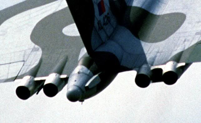
Following the other thread, here’s another oddball question. The Vulcan’s 200-series Olympus engines had smaller-diameter exhaust cans, but also incorporate a series of square plates around them. I can’t recall what these were actually for although I vaguely recall that it was connected to smoke suppression? Anyone remember what their actual purpose was? It’s annoying me now and despite having looked, I can’t find any definitive answer!

By: Chox - 8th August 2011 at 16:12
Moving the thread back to the previous subject again (seen as it’s been dead for a long time!), has anyone had any thoughts on why the sample pod pylons were placed outboard of the Skybolt fittings (where everyone seems to have assumed that they were fixed) ?
By: madjock mcgrok - 6th October 2010 at 00:17
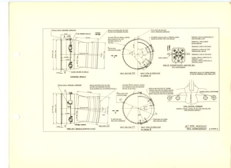
Moving the thread slightly back on target – the modified jet pipe end caps were fitted due to problems with the thermocouple cables chafing and giving false high temp readings- down route crew chiefs came up with some ingenious ways to stop this happening. I’ll see if I can find the Vol2 and track down the mod leaflet number and application date.
Cheers
Mad Jock
By: Chox - 5th October 2010 at 00:41
First off, thanks very much for the manual papers Flipflop – I will study them carefully and thanks very much for those!
Now here’s the odd thing – the sample pod pylons did (as the manual papers confirm) require the additional strength of the Skybolt wing ribs. But for some strange reason the pylons were not placed where the Skybolt and Black Buck pylons were attached:-
http://www.avrovulcan.org.uk/unknown/558_scampton.jpg
Thing is, I can’t imagine why they would have been attached further outboard. The only possible clue I can find is in the manual papers where it states that the pod tanks could have been used to carry fuel if necessary. Maybe the pylons were positioned in relation to the best fuel linkage route? I can’t think of any other reason why they couldn’t have simply been placed on the Skybolt position.
By: Flipflopman - 4th October 2010 at 21:10
They were indeed modified Sea Vixen pods, and as Robert Hilton correctly intimates, they were fitted to the Skybolt hardpoints under Mods2390 and 2392.
I’ll try and send you a copy of the Mod leaflet via PM. 😉
Flipflopman
By: Robert Hilton - 4th October 2010 at 19:32
Re the pylons Chox.
I assume they used the same hard points as the planned Skybolt pylons. There were a number of a/c fitted with them. The hard points were even used during the Black Buck operations for Shrike and ECM
By: Chox - 4th October 2010 at 17:11
Really? Think that might be the answer then, well spotted!
By: pagen01 - 4th October 2010 at 16:47
There doesn’t seem to be any definitive answer but my hunch is that they are actually Sea Vixen tanks… any thoughts?
I have no evidence either, but I’m inclined to agree with you, the pods have the same support stencilling as the Vixen aswel.
By: Chox - 3rd October 2010 at 12:07
Yes, boring to some but surprisingly important to others, particularly modellers who strive to get things right! As you might guess, the resin parts I purchased don’t address this point either. Nothing’s ever easy!
Airfix were a bit naughty with their Vulcan kit, as the kit features 300-series exhausts (or at least an approximation of them) but they keep on issuing transfer sheets with markings for 200-series aircraft, particularly XH558. Naturally, a lot of people who buy the kit don’t really care about such details as long as the model looks vaguely like a Vulcan, but the dedicated “nit-pickers” have a hard time putting-right such problems! I’m striving to build an accurate replica of XH558 for a forthcoming issue of the new Airfix Magazine (I can mention that here with no reservations seen as it’s a key Publishing product!), and I’m opting for XH558 in tanker configuration, but with sampling pods attached, as seen in 1982.
This begs another question if you have a minute Flipflop (ps, please don’t bother about the other drawing if it’s a hassle, I was just intrigued to know what the text says!). Do you know if there’s a drawing anywhere amongst the manuals which specifies the precise location of the pylon for the sample pods? I’ve got a fairly good idea of where they should go from photographs but as we all know, pictures can be a little misleading sometimes.
Course, the other minor mystery on this subject was how the sample pods were manufactured. One school of thought was that the filter shrouds were attached to Sea Vixen fuel tanks, but others have claimed that they were Hunter tanks. There doesn’t seem to be any definitive answer but my hunch is that they are actually Sea Vixen tanks… any thoughts?
By: pagen01 - 3rd October 2010 at 10:36
Boring to most people, I fully understand…
No fascinating FFM, I always wondered why one panel was shorter than the other when both were fitted!
By: Lindy's Lad - 3rd October 2010 at 00:57
Boring to some, but since I’m teaching aerodynamics and just covered drag, I feel that I can have another excuse to bring the Vulcan into the classroom (so to speak). Such details are lecturing gold.
By: Flipflopman - 3rd October 2010 at 00:16
I always assumed it was an aerodynamic modification associated with the ECM plate which was attached underneath? Did the fairing not appear on either side (or both) depending on whether ECM plates were attached?
It was indeed! This caused us quite a bit of consternation however when we were refitting the end caps and noticed the difference, and resulted in hours and hours of digging through the Mod leaflets and aircraft drawings as to the reasons for it.
It was indeed due to the Counterpoise panel fitted to the Stb’d exhausts and the vortices it produced. When the Counterpoise panel was fitted to the Port side, as on some Blue Steel aircraft, the panel was shortened, so as not to produce the same amounts of turbulent air aft of the jet pipes.
Boring to most people, I fully understand, but sometimes you have to have something to take your mind off things!! :D:D
*Edit to add …. Chox, that’s all I have at the minute, but I’ll see if I have hard copy to scan, in which the print might be legible*
Flipflopman
By: Chox - 2nd October 2010 at 23:30
I always assumed it was an aerodynamic modification associated with the ECM plate which was attached underneath? Did the fairing not appear on either side (or both) depending on whether ECM plates were attached?
Thanks for the drawing – that’s very interesting! Could you post it a teensy bit larger if you have a minute so I/we can read the text too? It looks like it clarifies the position of the plates pretty clearly but from what I can see it shows the pipes in half diameter so I can’t quite make sense of it (yeah I’m a bit thick doh!)…
By: Lindy's Lad - 2nd October 2010 at 21:13
Never noticed that before! Is it the same on ex-blue steel aircraft? I have an idea but I’ll let your best mate Chox have a go first…. 😀
By: Flipflopman - 2nd October 2010 at 21:07
Pagen01,
No worries at all mate!
Lindy’s Lad,
Sorry mate, that was more aimed at Chox to see how accurate the resin parts were! Have a hastily cropped picture though, which should hopefully show what I was getting at!
Flipflopman
By: Lindy's Lad - 2nd October 2010 at 20:27
Flipflopman, Without knowing what you’re talking about (got a comparison picture?) I’d hazard a guess at some sort of asymetric thrust compensation.
By: pagen01 - 2nd October 2010 at 20:01
Thanks for the clarification on my part chaps
By: Flipflopman - 2nd October 2010 at 14:54
Not the most clear picture, but it might give you a slightly better idea of how they were situated?
As an additional puzzle, have you worked out why the end caps on the Stb’d side were faired in smoothly between the trailing edge and the end caps, and the Port side were squared off with the trailing edge at 90 degrees to the end caps??? :diablo:
Flipflopman
By: Chox - 2nd October 2010 at 14:34
It’s hard to tell when the modification was made but it looks as if it was done sometime around 1970 as pictures of aircraft prior to that date seem to show the end caps without any fairings attached to them.
It was just a minor mystery I couldn’t explain, as I’m working on a model of XH558 and I purchased a set of resin-formed 200-series jet pipes which are intended to modify the Airfix kit (which features rather rough approximations of the 300-series end caps). The resin parts don’t feature the fairings but the accompanying instructions claim that XH558 has “an additional five angular fairings around the tailpipe for a different starter system” (quote). Not quite sure why the starter system would be in the end cap though! Anyway, at least I know what they were for now, and all I have to do is determine precisely where they were placed! Doh!
By: Flipflopman - 2nd October 2010 at 12:51
Tim,
Can’t help with when they were added, but as you suggest, it’s entirely reasonable that the end caps started life without the bulges, but as time went on, and thermocouples were being damaged due to the tight fit, a Mod was embodied to give them a little extra room?
Pagen01,
The thermocouples are actually in the jet pipe. The end caps we’re talking about are just that, end caps. The jet pipe itself is around 23 ft long, and protrudes from the trailing edge by around 3 feet, so the steel end caps simply act as a fairing and tidy the area up. As Lindy’s Lad says, the end of the jet pipe was the fashionable and highly uncomfortable place to put thermocouples back in that era!
Flipflopman
By: Lindy's Lad - 2nd October 2010 at 12:08
evn JP’s have thermocouples in the extreme end of the jet pipe. Nothing unusual. Designed to impale delecate places when extracting yourself from the jet pipe following a turbine inspection.:D
Oh and Spock – you have a short memory. 319’s are replacement caps… not original aircraft parts…


 Sign In
 October 1, 2010 at 12:40 am