At least no shooting game.
and no..the weaknesses of IRST is that it is not able to measure range directly and not really “all weather” sensor solution.
It looks to me like a Resolution problem.
SU-34 use standard AL-31F or so i heard. No TVC at all.
Accuracy are always relative terms. especially if one deals with classification. But if one wish for somewhat scientifically sound method, something has to be done. Errors are meant to be corrected through discussions.
The rest of the variables are in the “Pre-calculated variables” tab. There you can find the “working nuts and bolts” of the spreadsheet. It automatically estimates the loss budget, system noise temperatures and model some losses. The section in green can be edited but it can be left as is. I concept the sheet to be usable where the users can easily input variables they can find in the open source literature which usually very limited and let the sheet estimate rest of it.
For the MDS it always start from estimates of the system temperatures. This part of the sheet will estimate the system temperature.
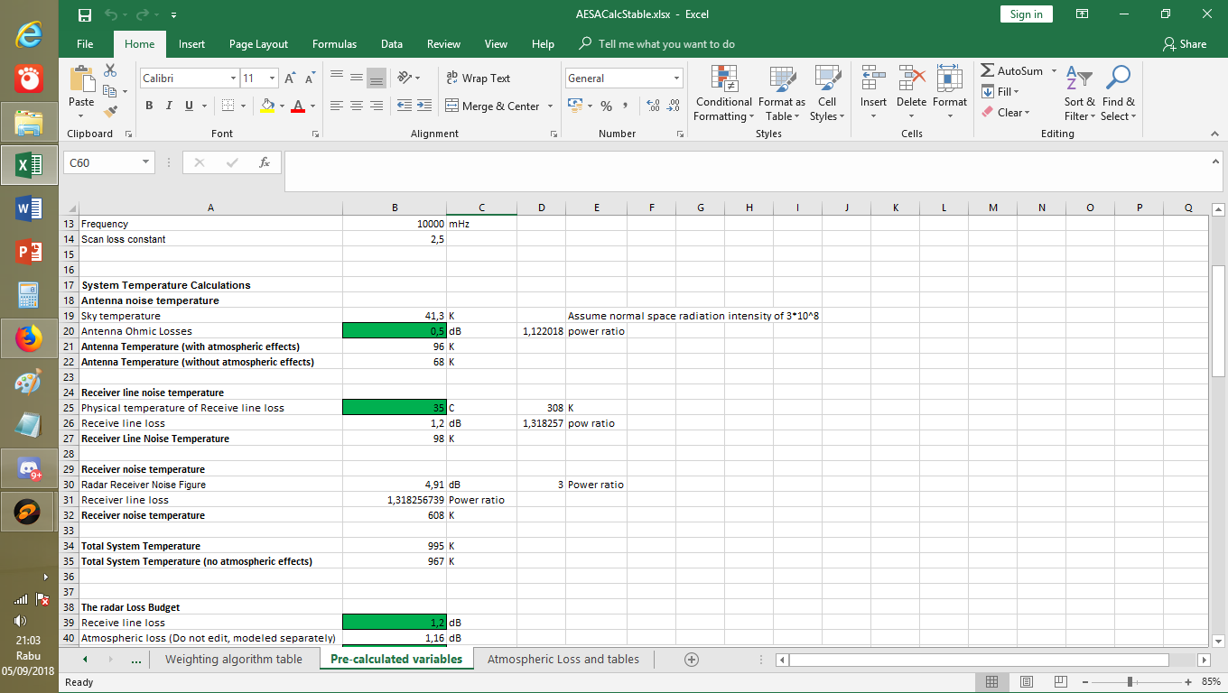
The loss budget.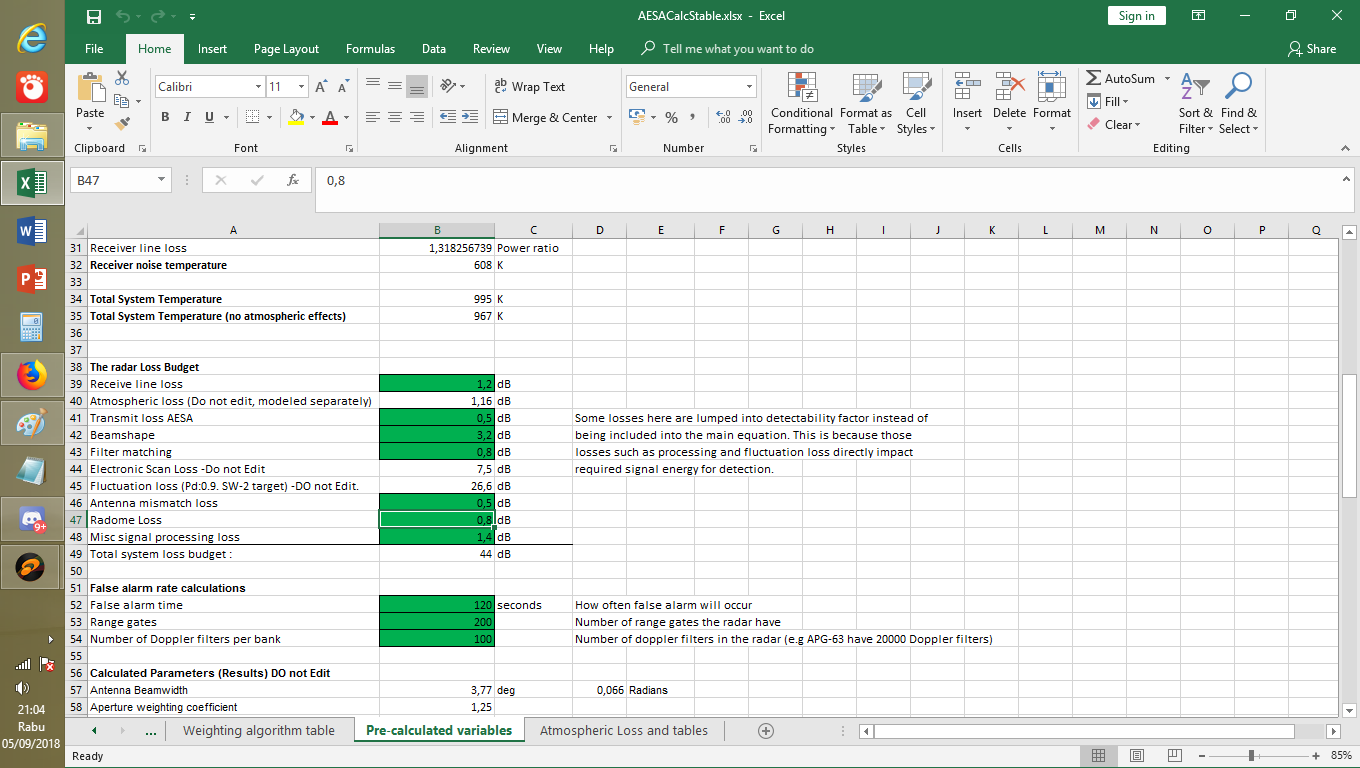
Most part are editable but can be left as is. The value are taken from typical loss value for radar in books like Radar Technology Encyclopedia and Basic Radar Analysis.
And this section is the important one as it consolidate and attempt to model pulse integrations. Here you can find how many pulses received and integrated.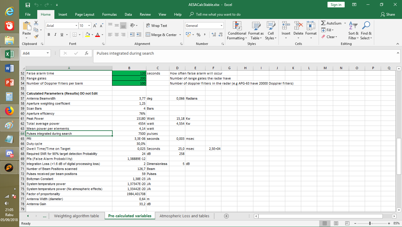
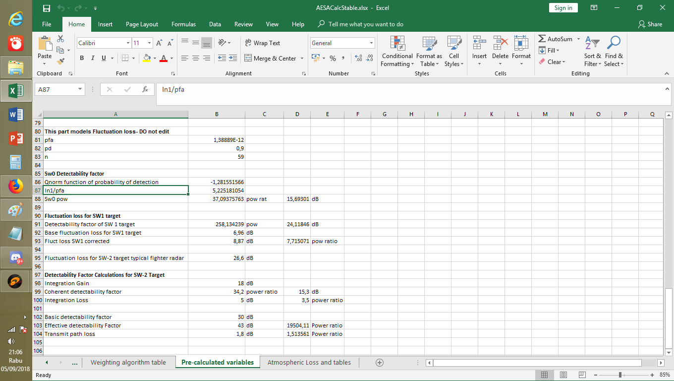
And then estimates of fluctuation loss.
Other variables like weather attenuation and prediction of radar receiver noise figure can be found in the Atmospheric loss tab :
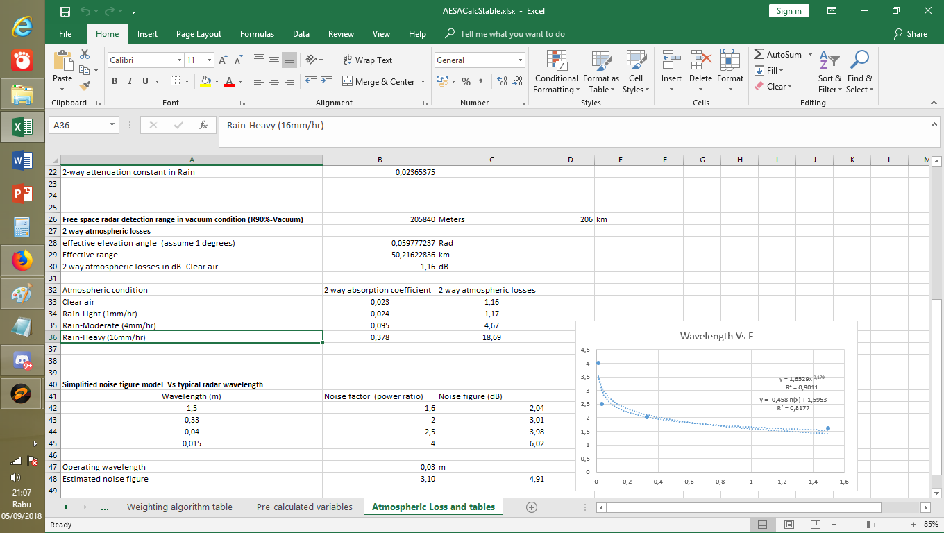
This part of worksheet are meant to be automated, it will estimate its own variables based on interpolations and simplified K.Barton model.
Another “automated part” is in the “Weighting algorithm” tab. Here you can find various tables regarding the antenna and supports for the drop down menus on the main sheet
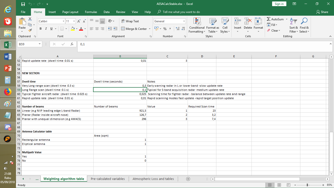
In this sheet calculations of antenna dwell time and numbers of beams are carried out.
Hopefully we have more news on Su-57’s EW suite.
Im curious tho about Himalaya, and the number of aperture it got. Since all current potentially threatening radar are monopulse, Su-57 would be benefitted from having wingtip aperture to conduct Cross Eye jamming.
I hosted interesting paper about Chinese T-R module development. By NRIET. It is in 1990’s but relevant especially if one wish to make estimate on Chinese AEW or Ground based AESA radar.
https://www.scribd.com/document/387389189/Chinese-ESA-module-development-1990-Era
Based on it i tried to make my estimate of KJ-2000 Radar coverage. This assumes free space range with only atmospheric absorbance and horizon as limit. No multipath (so observed RCS would be same as what’s being tested in RCS range, affected only by wavelength of the radar and not affected by path propagation. No lobing in coverage)
[ATTACH=CONFIG]262523[/ATTACH]
The diagram is for Indonesian readers but i think the X-Y axis are clear, it’s range Vs altitude. The target is assumed to follow Swerling 1-2 model with probability of detection 90%, update rate of 2 seconds due to electronic scanning
Legends are from top to bottom :
-Cakupan KJ-2000 berdasar cakrawala – Coverage of KJ-2000 based on Horizon
-Detection range of target with RCS of 0.5 sqm (in X-band)/ 3.9 sqm (in L-band), Detected at 772 km.
-Top of the envelope
-Bottom of the envelope
-Patrol altitude of the AEW : 11000 meter
-Estimate of detection range against KF/IF-X
-Estimate of detection range against JSF
-Estimate of detection range against F-22 Raptor
My assumed technical specs of KJ-2000 radar which i use to make the calculations.
[ATTACH=CONFIG]262524[/ATTACH]
thoughts are welcome.
I wonder, how many JASDF’s F-15 already got to Kai Standard ? and will they equip AESA to their fleet.
The simple shape would easily follows the wavelength dependency.Complex geometry Aircraft.. that could be a long way.
My paper search so far however was not lucky. My idea is to try actually make various shapes and run it through computer modeling then attempt to relate it to the natural wavelength dependence. However I’m limited to the code that available to me. POFACETS alone might not be enough.
Quick Update. Replacing the wavelength with Frequencies. User can now input frequency instead of wavelength. As why i picked MHz that’s because it seems to be more convenient than GHz or KHz as well, from my experience, commonly people using radio use MHz and GHz is more often for Satellite communication or WIFI.
[ATTACH=CONFIG]262386[/ATTACH]
.
Sputniknews have similar story BUT different aircraft.
[ATTACH=CONFIG]262385[/ATTACH]
This seems to be more legit Kowsar.
Kinda hard to expect new V/STOL especially in engine department, as the R-79V engine seems not going anywhere in terms of development. Engine alone may take 10-20 years to perfect.
1-This isn’t a big issue but i think it will be easier to use if you let the user input frequency in Ghz instead of Wavelength in meters.
2- I think the estimation of RCS difference might still be too big, at least for VLO aircraft.
Recently re-surfaced video (posted by mig31) indicate that at distance of 30 km, P-18 can’t detect F-117 with 3 out 4 of its frequency setting.
1.I agree thanks. Although i think MHz would be better.
2.As i mentioned at post predating the update post. The approximation works best for simple shapes, though my observation suggest that it might be applicable to real aircraft. That is of course limitations which i assume the user would be aware of. It may over-predict the possible RCS value. The problem is of course i haven’t able yet to find a good “fudge factor” to take account of such uncertainties. Lowering the dB value based on the XST image might work but will it be applicable to any other object ?. Thus why i release the sheet as is.
Rough extrapolate from the table
If radar height was 6.35 meters, P-18 will detect targets with RCS= 2.5 m2, cruising at 6km altitude from 132.5 km, reduce RCS by 10 times and we get 44% detection range reduction so F-117 RCS is smaller than 0.025m2 at frequencies >140 Mhz.
If radar height was 10.35 meters, P-18 will detect targets with RCS= 2.5 m2, cruising at 6km altitude from 180 km, reduce RCS by 10 times and we get 44% detection range reduction so F-117 RCS is smaller than 0.0025m2 at frequencies >140 Mhz.
Do you have any suggestion on possible fudge factor ?
Your extrapolation however i found rather complicated mainly because it requires vertical coverage diagram and taking account of multipath. These would make it hard to apply any result of the extrapolation in other radar, which may have different lobing structure on its vertical coverage.
Latest Version :
http://www.mediafire.com/file/s8ea52zoc8zzf17/AESACalcStable.xlsx/file
What’s new ?
The addition of :
1.Target RCS conversion tool.
Following my thoughts on the above post, i decided to add the RCS tool into the spreadsheet to facilitate user to predict the upper and lower limit of RCS of his target.

2.TRM/Radiator module finder
This new sheet will attempt to predict the number of TRM an antenna can have, based on assumption of half wavelength spacing and fill factor. The antenna fill factor determines how many modules will occupy the antenna face. 100% indicates that the antenna face is filled with TRM. This might also reflect the technology and considerations during the design of the radar. e.g module dimensions. Current trends apparently moving toward tiled architecture due to simplicity of assembling and the fact that one can utilize most of the antenna area.

This spreadsheet also contain simple antenna area calculator to allow quick prediction of area of common antenna.
3.New antenna.
Given that not all AESA radar are built in axisymmetrical antenna (e.g KJ-2000 AWACS) New type of antenna and subsequent supporting variables have been added in the main sheet.

Should the new antenna selected, user can input the dimension of the antenna beside the number of module it have. Should other antenna type selected the width and height variable will be ignored during the calculations.
Another addition is the “scan time” in the result section.
The scan time/update rate is provided to facilitate user to view how fast the radar scans its assigned sector and relate it to range. Faster scanning may yield shorter range but rapid update suitable for mid-course update of a guided missile or vectoring interceptors, while long scans would be beneficial for detection of low RCS target.
Critics and suggestions are welcome :D, Thanks.
lead designer mentioned it to be in the ball-park of the F-22, between 0.2 and 0.5 m2. Band was not indicated as far as I know. Everybody implies X band but it may not be the case! Maybe somebody has more information or can correct what I write here.
As said, this is a complex and sensible matter and no side is going to disclose all the tricks in public. Hence the scarce progress in this perennial thread discussion…
The thing is that NO one so far mentioning any frequency figure. All people mentioning frequencies so far are those doing simulations like Kopp or others so basically it’s not really official. Or old information like one image i discussed on my AESA radar calculator thread.
For some reason all discussions regarding stealth or RCS often neglect that elephant sized hole and as we see people just stick on 0.000x value. Russians so far never really disclose anything about in what frequency that RCS value achieved. The best remarks they have was from their VHF radar manufacturer about Chinese Ballistic missile which have 0.001 in X band but much larger 0.6 in VHF.
What exactly the RCS design goal for Su-57 ? and for what frequency/wavelength ?
Touting values are of no meaning if one don’t include the wavelength or other information supporting the value. Saying it only wants to go 0.1 have no means.


 Sign In