No offence, but I don’t need expert knowledge or mega-eyeball-radars to be able to tell that the underbody would have a lower RCS if those bumps and bulgers caused by the engine intakes were flattened out and filled in for a uniform, rectangular underside.;)
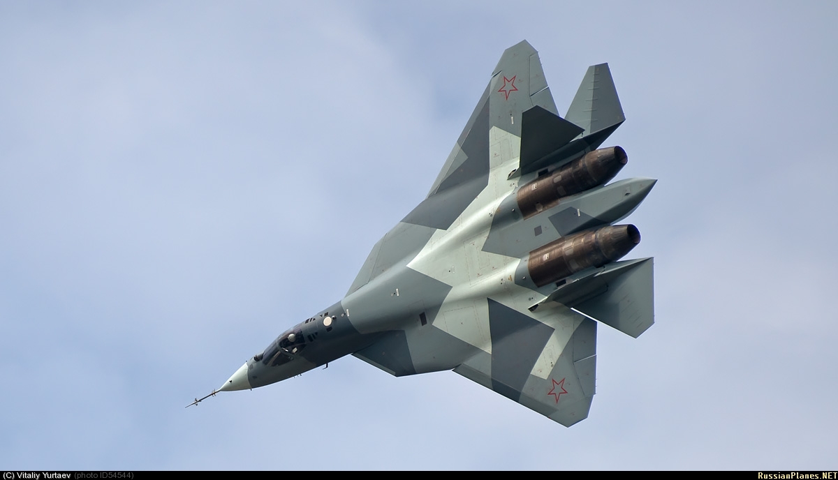
The intakes have employed considerable faceting on the inside walls of the intake and sloping of the outer walls and alignment for the frontal aspect (see pic below- you don’t need mega-eyeballs).
As Bergidum has already pointed out, it is the subtle differences in incidence angles that make all the difference, and it is apparent from that pic that they’ve done much data crunching mit supercomputers & software.
http://sukhoi.org/img/gallery/wallpaper/1_29_01_10/1002101_24.jpg
Regarding the engine cowlings, that’s a ‘wait and see’, but it’s probable Sukhoi engineers consider their circular cross section (as a scattering property) will not compromise the overall RCS of the aircraft.
One thing you can use your eyeballs for is to see which of the current 5G fighters has the lowest profile, now I ask you do you think that is good or bad for stealth?
As for the second stage engine it will be a totally ‘clean sheet’ design and not descended from the 117- which itself is no slouch, generating similar dry thrust than a ‘wet’ EJ-200 and leaving the blk60’s F110-GE-132 standing.
I wouldn’t expect the 2-D nozzle to make an appearance anytime soon, and may only be destined for the 2nd stage (Izd.129) engine.
When pressed on the above, Pogosyan stated it wasn’t worth speculating [on the Izd.129] as it’s too early. However, he said concrete details would be made available by MAKS 2013.
http://www.sukhoi.org/img/gallery/wallpaper/_SPN8702.jpg
http://www.sukhoi.org/img/gallery/wallpaper/_SPN8698.jpg
http://www.sukhoi.org/img/gallery/wallpaper/_SPN3452.jpg
http://www.sukhoi.org/img/gallery/wallpaper/_SPL8853.jpg
http://www.sukhoi.org/img/gallery/wallpaper/_SPN3372.jpg
http://www.sukhoi.org/img/gallery/wallpaper/_SPL8704.jpg
When we say S-duct, we specifically mean inlet ducts specifically shaped in a way to minimise radar return from the engine compressor face. We mean the ones seen in B-2, F-22, F-35, the ones that are designed for stealth even at the expense of lower pressure recovery.
The inlet duct on the 1.44 is not an S-duct. Is it straight? No. But it’s not an S-duct.
I’m not claiming the 1.42 was a stealth design, I would, however, define it as RO (Reduced Observability), with an S-duct as an inherent RO feature.
Imho, the nearest design contemporary of the 1.44 is the Eurofighter Typhoon with an almost identical RO design philosophy (although you could argue that the 1.44 has a more LO optimised upper-forward/cockpit structure):
The Eurofighter Typhoon cannot and is not classed as a stealth fighter (see fact box). However the consortium did take measures to reduce the aircraft’s radar cross section. Many of these Reduced Observable (RO) features were tested over the years at BAE Systems covered radar signature range at BAe Warton near Preston, NW England. Some examples of this design include; the intakes which are shaped so as to hide the engine compressor blades, the sloped intake sides, the fuselage recessed medium range weapons, the wing hardpoint placement and design, radome construction, etc. In addition Radar Absorbent Materials (RAM) developed primarily by EADS/DASA coat many of the most significant reflectors, e.g. the wing leading edges, the intake edges and interior, the rudder surrounds, strakes, etc.
Didn’t the 1.42 also have S-ducks? (dark grey cylinder:confused:)


’52’, 18/08/11:
Some high res. stunners (Copyright Marina Listseva, not for commercial use):
http://pics.livejournal.com/fotografersha/pic/0062gty5
http://pics.livejournal.com/fotografersha/pic/0063ce1p
http://pics.livejournal.com/fotografersha/pic/0064qgfp
http://pics.livejournal.com/fotografersha/pic/00630sdk
…and this one’s for you Witcha:
http://www.npo-saturn.ru/img/photo/2011/1302260548_1180608585_Sukhoi_T50_sc2.jpg
havaarla, you’re disrupting my boundary layer:

Look out haavarla!! She’s about to jettison!!:eek: (though not dangerous [I]per se[/I]):D…

’52’, 13/08/11.
However my question would be, what is the aim behind this angled position? I mean the T50 is an early prototype mainly for flight testings and we know that these engines will not be the final versions anyway, so one would expect Sukhoi to use a position of the engine, that is as easy as possible right?
Does it have an effect if the compressor face is angled to the front and inverted in regard of radar reflections?
CFD/FEA and other CAD/CAM packages have come on leaps and bounds since even the F-35 was designed. In conjunction with extensive wind-tunnel testing, the margin of error has significantly reduced and the design parameters should match the envisaged ‘real-world’ flight testing quite closely. Bogdan said @ MAKS that they’ve completed the ‘Easy’ stage, and anticipates that the flight envelope will be opened-up for the ‘Medium’ stage shortly.
Hence, the T-50 can be considered much more than a conceptual prototype, and something more akin to an EMD aircraft. As for the engine alignment, the engine & blocker will be an integrated solution whereby managing the radar returns will be a function of airflow efficiency under different flight regimes, hence the various gizmos glimpsed in the intake (including what appears to be a faceted DSI-type ‘bump’).
The attachment below details Japanese engine blocker research for a conceptual 6G fighter, I’d expect something similar to be adopted on the PAK-FA.

so now you went from saying saying that the compressor face is a device, which is you think is a FOD screen.. that deep down in the intake.. and some how creates a ridge that causes brown spots.. ok..
Which way is that engine pointing?….and which way is that ‘device’ pointing?

Amazing how my speculation as to the location of that device has brought you out in uncontrollable juvenile spasms! Why? is your desperate fantasy falling apart so completely? BTW, Are you a juvenile? I’m just curious because you repeatedly hide your lack of knowledge in technical/engineering, economics etc.etc. fields behind a flimsy facade of humour, that’s OK if you’re aged 13, but if your an adult- that’s a trait of a severe psychological flaw.
Could you direct me to a thread you didn’t defecate in? Thanks.
There is nothing wrong with MKI engines. IAF can better spend their resources on more useful things.;)
Erm, I don’t think the AL-31FP will be able to handle the AESA and other avionics upgrades’ power requirements, also if the airframes are to be strengthened and treated with RAM coatings and other RCS reduction measures there will be a significant increase in weight.
I’d expect Salyut’s AL-31FM2 (29,200lbs), or the outside chance that the monster AL-31FM3 (~31,000lbs) will be installed.
Once the price negotiations are completed and contracts get signed, I’m sure concrete details will emerge, for the ‘Super-30’ will be Irkut’s rival to the Su-35S on the international market.
In the current economic climate, the F136 is a case of throwing (borrowed) good money after bad, there’s simply no vision for the timescale where the programme may become economically & militarily viable.
There are some senior executives in the US defence industry that believe Congress will take out up to $1,000bn from the core Pentagon budget over the next decade. The first port of call for the axeman will be F-35 procurement, so don’t expect unit cost to fall sub-$100mn anytime soon (if ever).
Ok tell me how it ejects the FOD as there is no vents in that area?
It just sits there disrupting the flow of air until it lands and ground crew then crawl into the LONG intake to clear it??
I have no idea! Maybe they use small children. I’m just speculating- however, I’ll make a statement of fact that given that we know the precise alignment of the engine (given HQ rear photos) the two pics of that thing show it neither canted inwards nor downwards. So either both pics are faked (with the obvious mistake of the cant- because both pics show it face-on), or it’s something else altogether.
Here’s a pic taken from the intake mouth of an Su-27 by our very own Ken (Flankerman), gives you a good sense of proportion and scale, given that both PAK-FA pics are taken several metres away from the intake, I mean c’mon :rolleyes:
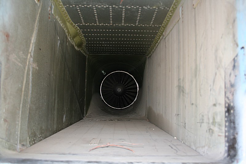
That dirty area is still within the mainwheel well area, if the blocker is there then the intake must narrow a significant amount for it to be “circular” in cross section…
Actually, it doesn’t, it’s clear of the ‘bulge’ that houses the wheel. I’m not saying it’s a blocker, imho, it’s a FOD screen. It fits the bill perfectly.

Mr. Hotdog if you’re going to pedal that (now infamous) pic against the ton of high-quality pics that became available last month, then at least use the brightened-up image which shows the direction that thing is facing.
I think you’ll find it isn’t easily reconciled with the two engine placement images I’ve already posted- in fact, not at all. Thanks.
so why would this device cause two dirty bars.. on the outside..
Dirty air bleeding from the underside auxiliary air intakes, coalescing at the very slight ridge that has formed where the devices are installed.
The real compressors are ~1/2 a metre higher and angled (converging on the nose).
So that ‘thing’ is mounted too low and is pointing in the wrong direction.


 Sign In