So your assumption is that the undercarriage retracts into the SIDE of the intake wall? Hmm…look closer (look at the underside picture.) It retracts at the bottom of the wing…right where your supposed upward curve is supposed to be (which it can’t be).
Let him be over_G. Everyone knows why he’s throwing his toys out of the pram.
Once more…simply because you can’t make an argument…doesn’t give you the right to make a personal insult.
He’s doing too much fuss w/o enough information
It is a question that needs explaining…All it is.
But i still would like to know what is this

It has a variable intake…Which I asked what are the implications of stealth to an aircraft that has movable intakes…and a movable lerx
@ Kapedani, in the previous thread djcross opposed you but you are still pushing your own point of view which you are trying to present as an universal truth. Are you more competent than he is in this field? Are you an engineer or a scientist working in the aviation industry? An aviation journo perhaps? We are all lacking solid info and hard data on this plane and you are trying to judge it after several pics and videos have been released From what I could conclude I would say that you don’t really like what the Russians have achieved and you are trying to downplay that any way you can. I bet you could do much better than this. Or can you really
Again silliness of this level shouldn’t have any place in THIS forum. “You don’t like the Ruskies so thats why you’r asking questions!”.
I havn’t heard Mr. Djcross talk about the intake geometry in here. I’ve heard a lot of him saying how he automatically figured out it has a “marble ball” RCS from the 2 pictures available.
I’d have to conclude if he was an “engineer”, he’d be a pretty poor one for making such a statement. (BTW I’m an engineer as well albeit not aeronautical…although thats what I started out as). This isn’t a personal issue…regardless how you may want to make it.
There’s a very simple question I’m asking…where in that cylindrical nacelle…is there room for any deep S-curve to hide the engine face from ALL (or most) frontal angels?
Answers?
This for example (and all the others before it) are not answers for a simple reason: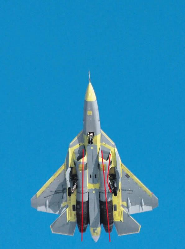
a) the intake geometry can’t possibly be that way (ie you can’t narrow it to the point that it makes your drawing work)
b) Even that forced and unrealistic geometry leaves lots of frontal angles where the engine face can be seen.
Nor is this:
Because the intake starts where the engine starts and ends halfway through. Thats great, except that there’s one problem…that being the undercarriage which retracts at the TOP of the wing root, preventing the intake to curve upward. In fact it can be seen almost certainly from all pictures…that it curves downward to avoid the undercarriage bay on top.
The question then is, if I’m looking straight at the aircraft and slightly downward…do I get a good view of the engine face?
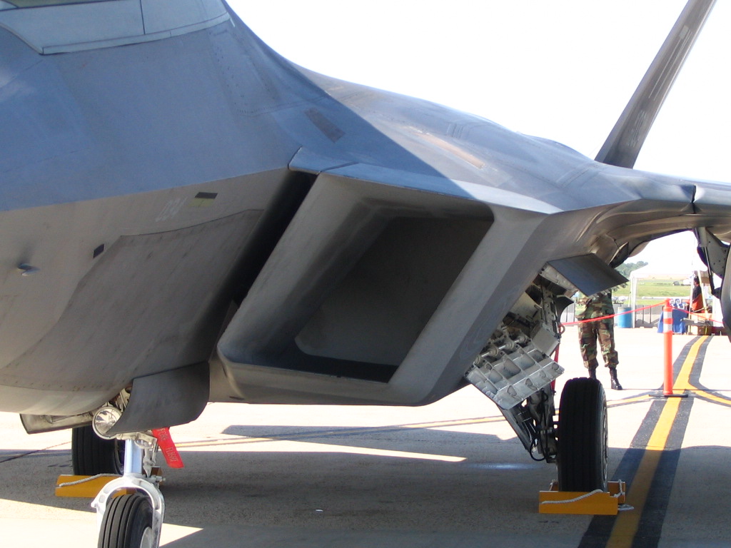
It was shown how the F-22 externally its intakes and design “appear” to 100% straight and pretty much inline with the engine face. Yet we all know that the compressor face isnt visible from the front.
Seemingly that mere fact only applies to the F-22 and obviously any other aircraft is inferior.
The F-22 very clearly doesn’t have anything of the sort as engines placed in straight cylindrical nacelles…forming an unstealthy bottom.
The problem with some people is that they cannot comprehend a different technical solution.
Yes I think we’ve gone over my personal problems pretty well so far 🙂
Now please explain the “technical solution”… 😉
An intake like this for example:
Would clearly not be sufficient. And this intake also doesn’t take into account the undercarriage bay (being on top)
The issue can be clearly be seen here

Except that the landing gears retract just where your intake duct is supposed to be 😉
The undercarriage prevents this from happening in every possible way. It doesn’t retract into the nacelle. It retracts into the wing root there.
This is the F-22 layout, and while it is very stealthy, it forces a relatively small internal bay and limits usability of thrust vectoring. If they are offset vertically the engines can be at optimum distance from each other for thrust vectoring, and leave a lot of room for internal weapons – but you won’t have a “block” body shape. This by itself doesn’t necessarily make the plane less stealthy, remember the YF-23
Except that the layout of the YF-23 is entirely different in the way it attempts to hide the engine face (and still fails apparently) and in the layout of the bottom of the aircraft. The T-50 on the other hand has a pretty conventional underside with cylindrical straight nacelles protruding from the aircraft.
It can’t possibly have the same stealth characteristics of the YF-23, even though it seems to try and copy it.
That’s exactly how the intake works.
Since there’s an elevation difference, you can see the bottom half of the engine, in the top of the intake. The top of the intake (duct) has the wheel housing, which blocks the rest of the visible engine. Ding ding ding!
Except that thats not what happens. The intake slants downward in order to avoid the undercarriage at the top, and then slants upward again. But the bottom has nowhere to go, so the level of the curvature has to be pretty limited. Thats about the only possible curvature they can make inside those intakes.
That still leaves lots of angles where the engine face can be seen
Compare to this for which there is no room in the T-50 for.

This drawing from 2004 (probably a leaked drawing) is almost identical to the actual T-50 that flew. As can be seen, the engine inlet design is pretty much just as I explained it…and you can see the engine face from lots of frontal angles.
For one thing, unlike the Raptor, PAK FA has confirmed variable intake ramps
And what are the implications for stealth here?
“So tell me Eminent Cousin of WiKapedani twice removed, how does your F-22 fly with its intake covers deployed?”
-“I have no idea, but WiKapedani says it’s something to do with the S-ducts!”
Hey Foxmulder!! try your geometry lines on this, looks like~ 1/3 of the compressors will be visible:
Would you like to point to us the intake covers on the F-22? 🙂
If you can’t figure out the difference between the intake and engine configuration of the F-22, and the T-50…there’s very little I can do to help you.
Surly Kapedani we all can see that the wheels prodrude well inside of the inlets ducts.
Slightly on the side…but mostly on the TOP of the duct. Now this still doesn’t show where there is room for an S-duct in the horizontal at all. If there was one, where does the other side end up? In the weapons bay? (and forces the duct to be slanted down instead of up…but again this still leaves the possibility of some very wide frontal angles where the engine can be seen)
Well for what it’s worth.. i assume it
Facto: Russian labour salleries are far below US salleries.
Facto: Russian engineers and researchers do have the ‘know how’ on many different fields, soo why don’t you explain why its imposible for the Russkies to get this right?
A good rule is that there are always several ways to meet the same goals when it comes to advance aviation R&D.
Aviation history has proven that over and over.
Typical to go about that 20 year US advancment.
The most flawed assumptions ever made (except the first one)
I don’t think anybody said that, but it could happen. We’ll see soon enough.
Remember there are many other stuff like engine consumtion, mission range, weapon capasity, air to ground capability, Low & high speed turning ability, well the list goes on..
I’m not arguing about the performance capabilities of this thing. Its its stealth I’m arguing about (not getting into the sensors and electronics)
They already use RAM coatings on their fan blades on the Su-35, which greatly reduces the RCS. In addition they could use F-18E/F style radar blockers. Between these two techniques, I imagine that there would be a significant RCS reduction.
Yes they did. The…magnitude…of reduction however, isn’t the same.
Its clearly a design straight out of 1990…just not as good or as complete.
Now thats pure trolling, you are not fooling anybody here..
If trolling is me expressing my opinions of what I see…then clearly I am. With that arrangement on the bottom side of the aircraft, this is a pretty poor design for stealth. Certainly not all-around-stealth. Then the question of the inlets leaves open another possibility. Otherwise, pretty conventional stuff already seen 20 years ago, which is why I said what I said.
Your thoughts are your own, still only speculation since you have zippo on how far the Russkies have come on RAM fielding.
Why are this debates all the time bringing up the RAM coating issue..?
Pls wait until we see something applied on later Pak-Fa versions.
🙂 Once more…I ain’t the one speculating here. I’m only pointing out…that SOME OF YOU are speculating. There’s a big difference.
See I didn’t even mention RAM at all. Precisely because I can’t say anything about it. What I mentioned was the way the engine inlets are arranged, and why this may provide a problem for the supposed CLAIM that this aircraft is “better than the F22!”.
Ahh…but I must be speculating…Even though I’m talking strictly of what we can already see (a rather unstealthy bottom of the aircraft and inlets)
I’m in danger of repeating myself here.. thats pure SPECULATION on your behalf.
In case you havent paying close attention, Sukhoi have manage to keep this program under a tight wrap uptill now. I bet they have much more up their sleeves
Again…same thing. Typical answer is always “well the Russians are secretive and they must have something better…clearly”. And then when someone comes and says “wait a minute, you got any evidence for anything you’re saying?”…the response is the typical “stop speculating that they don’t!!”
Here’s a clearer image. Now try and fit some shapes into that 🙂

Is just because the 22 is old, time has passed, and things have improved.
🙂 Yes things have improved for the Americans…since they spend 20 years improving them. You can’t assume…that out of the blue…after 20 years of inactivity, the Russians managed to gain all the knowledge the US gained…and added more…at a lower price…in half the time…etc etc etc 🙂
You see the absurdity here? I’m not saying they didn’t! I’m saying the chances of it actually having turned out that way, are better than of me winning the lottery.
And you can’t simply assume that since the T-50 flies in 2010, that it is “better” than the YF-22 since its newer.
Its clearly a design straight out of 1990…just not as good or as complete.
Now the Russians have put a lot of things on their brochures for all their weapons claiming similar performance specs as western counterparts (at 1/3 the prices of course). But in most cases reality is far from the advertisement. I’m sure they’ll say…”its as good or better than the F-22…and we managed to do it in half the time, in half the cost, in half the…” Of course!!
Note MLG retracts into intake walls, and engine ‘humps’ (which slightly diverge to nozzles).
Not you WiKapedani- you’re blind.
Again…about the prick part 😉
First of all, again, thats not a hump but the way the plane sits on the ground.
Yes the engines are slightly above the air intake…but thats because the wing is in the way. The question is…is it ENOUGH to provide full covering for the engine face.
1) Engine and intake is not at the same plane;
As that picture shows, they’r very much so in the same plane.
The middle of the engine is about where the inlet starts. The bottom of the engine is where the inlet ends as well. Thats the same plane…
And as you will see if you pay attention…the inlet curves DOWN in order to avoid the undercarriage. Now this leaves the problem that the engine face could be exposed from the front to a wide angle.
Same here:
If I’m looking straight at the aircraft I’ve got a pretty good view of the engine face. (the way you drew it…which is highly deceptive)
————————
Now what the Ruskies did was…in all likelihood…put a blocker…as getting an S-duct curvature on that intake to cover the engine face fully seems like an impossibility. The question is…how effective is this blocker as opposed to the measures taken on the F-22?
MY opinion…is that it will be nowhere near as effective. Clearly…some here will say thats not the case and the Russians have discovered something here thats better then everyone else…otherwise…why would they do it (:rolleyes:) But these are all…opinions…and like a******…they all stink.
YF-23:
Attachment 181257
Bye-Bye, WiKapedani.
As I said…it would be so helpful to everyone if you could be less of a prick. We’re talking about F-22 here
Are there any close up pics of the F-22A inlets duct out there?

How effective? tell me please
Thats not up to me to tell you 🙂 I never claimed it had one…nor am I in the business of fantasizing. Thats Otaku’s field.
Btw, i’m not saying the t50 does not have s-duct shape, is just that is not that necessary
I’m saying it.
The big deal is to cover the engine, BTW this is a bit more complex, because we are talking about a wave, so even your open S-duct could be less effective than blockers.
Yes, thats why the extent of the curving matters as well. The question is…how effective are the covers?
Not that I’m expecting an answer from you…I’m just saying these things so that you (not you personally) can keep them in mind…and not degenerate in this forum like the masturbation-fest of 12 year olds at MP.net
The s-duct was required because RAM did not have the strength to resist the temperature and mechanical forces induced by the airflow.
Now it can
The S-duct is a old technology.
😀 ah yes the best argument in the book “well the Russians just are better at it”. I’m really glad the Russians have discovered something better than the S-duct and managed to also make their turbine blades out of RAM (along with discovering milling technology for their aircraft’s skin the US has been using since the 70s).
…but the problem still remains that there’s preciously little (or no) evidence the Russians are anywhere near the levels to have developed such technologies other than assumptions that SINCE they haven’t used the same degree of curvature in the engine inlets as EVERY stealth aircraft has…THEREFORE they must have invented something better.
That…or they didn’t.
Inferiority complex being covered up by failed superiority complex. Sounds like this sferrin guy around here, along with a few others.
I think an inferiority complex is extremely hard to see…when you actually have one. You need something else to compare to…after all. Thats where we come in 🙂
Because it can’t have blockers? because the S duct thing is that important?, i would wait for some pictures of the intake first.
Even with S duct, both the f22 and f23 did show clearly it fan at some ranges of angles
Of course it can have blockers. The question is…how EFFECTIVE are they as opposed to the measures the F-22 takes?
Secondly, you can’t see the F-22s engine face from ANY angle. And the way it is ducted inside also makes a difference in preventing reflections from making their way out.
Hmm. 350-400 @ EUR80-100M each over 10-12 years?
First of all if you’r paying 80-100 mil for this thing…you’re getting screwed pretty hard.
On the other hand, if you think Russia will produce 350-400 of these guys even in the next 30 years…you’re playing with yourself too much.
As I said in the begging, congrats to India for its new fighter.
I give up you can not comprehend
Oh I comprehend quite well…and trust me I appreciate your efforts.
Here’s what your carefully laid out drawing misses through.
1. The engine face and the air intake are nowhere NEAR as misaligned as your point out in your picture. They’r practically in a a straight line.
2. The duct dimension isn’t going to be as SMALL as you point out.
Now you see what happens?
PS: Again, the duct doesn’t go UP into the wing roots. Theres an undercarriage there and there’s structural work. It goes DOWN. And it doesn’t go anywhere sideways as there’s weapons bays on one side, and a straight cylindrical face on the other. Now I’m open to all possibilities here…but they seem pretty limited.
Kapedani:’It would help immensely if you were less of a prick.’
You seriously expect Putin’s cyber-clowns are here to be helpful? Perish the thought.
Ohh…I seriously would expect nothing more from most individuals on this forum (very unfortunately).
Here’s a possible solution. As the duct goes up and over the retracted wheels, they get narrow from top to bottom, but they widened from side-to-side, maybe even extending into the wing area. And then they narrow again(side-to-side) and widened(top-to-bottom) as it comes down over the retracted wheels before connecting to the engine face. During the whole course of the traverse maintaining a constant total cross-sectional area to prevent restriction of air flow. By doing this, there would be just a slight bulge over the part of the fuselage-wing root. This bulge has an added benefit of helping lift due to the Bernoulli effect.
:rolleyes: Wow a lot of effort there to defy physics.
First of all you’re still not getting that in order for the duct to avoid the undercarriage…it would have to go UNDERNEATH it. Secondly there’s preciously little room for any horizontal shift in what is basically a straight cylinder.
Second of all, there’s no way this thing is widening from side to side into the wing area. Theres an undercarriage there, structural works, weapons bays.
Now there is clearly a DOWNWARD curve in the intake to avoid the undercarriage which then goes up again into the engine face.
The question is…is this anywhere near enough to cover the engine face from many frontal angles…and even if it does…is it anywhere near as effective as the measures taken on the F-22?
I have my doubts here…but I await to be enlightened by Otaku 🙂 (as we all surely will)
Keep it up, your both funny
I know I’m funny. Thanks. But fitting a single line down your intake there is a very easy way to avoid the point 🙂
Now…try fitting an actual DUCT down that line of yours 🙂 As I assume the duct in there isn’t anywhere near as skinny as your single line.
See the problem?
Now take a side view of the aircraft. Try and fit an S-curve in the vertical plain (making sure to avoid that undercarriage bay on TOP (and one would assume major structural work holding the wings together).
——–
Now…again…do this with an appropriate diameter duct…not a single line 😉
There surely is SOME curvature in there. The question is, how effective is this?
Ok. My one dimensional friend,
Air trunk and the dimension of the inlet wont be the same, here a drawing for one possibility;
🙂 Yes thank you. How did I not think of this!
Now try and fit that geometry to the T-50s engine nacelles and intakes 😉


 Sign In