original
photoshop
The point seemingly lost on a few people here is that there are issues with both photos… the same issues.
The “radar blocker” or front vanes or what ever you want to call them appear out of proportion and like too large in diameter for an object that is what? 2 meters inside the intake.
Why is there so many variations of the same night time picture?
Each one that has appeared on here has a different amount of lighting applied to it.
But one fact that really makes me laugh is that how on earth can so much lighting appear so far down that intake, unless there was a lighting source lower then the photographer? ie: headlights from a vehicle.
When you look at the photo which shows the whole nose section of the plane it appears to be a photo taken with a flash.
Yet the shadow on the “radar blocker” or whatever is only just lower then the shadow extending from the LEVCON into the intake?
Until we see a nice clear picture taken in broad daylight… Im not buying the one taken at night for now.
For all we know the photoshopped image Kapendi used was the first rendering which made it to the net? It was so blatent a fake image that the other was rehashed and cleaned up?
I’ll wait for better pictures….
One more point:
Where are the spill doors???
Cant see any on the sides internally?
Behind the radar blocker in the Super Bug’s inlet you can see fan’s blades with IGVs – same apply to T-50 except it doesn’t have radar blocker 😉
Examine closely these two pictures :
Notice the black blades in the Flanker’s inlet – those are Inlet Guide Vanes, if you now look at the T-50’s inlet this “radar blocker” has exactly the same shape as AL-31F’s IGVs. Weird 😉 Notice also, the dashed circle in AL-31F and in PAK’s inlet – again it must be coincidence :rolleyes: If you look carefully then the fan blades in AL-31 become clearly visible but I think they are even more visible in T-50 picture ( between ladder and third guide vane from right). There is also something like a wire which is going through every blade of 1 stage fan in AL-31F and this is visible Flanker picture and (I think) in T-50 picture.
This is an engine you’re looking at and no, it doesn’t have 9 meters.
T-50 on that picture doesn’t have ram coatings, no radar, just basic airframe with basic systems but it must have an engine radar blocker :rolleyes:
That picture of the T-50 intake still doesnt gell with me.
We know that Kapendi’s picture was photoshopped.
Look at the “depth” of the intake of the T-50 compared to the Su-27 intake.
You can see its a nice looong tunnel. Yet the T-50 picture shows no such depth and appears to be just one meter from the leading edge of the intake in terms of scale.
Yet we all know how long the intake is!

Um…some strange things about these pictures…??
The shadow is missing from the LEVCON on the vanes.
But.. not only that, blind freddy can see its photo shopped.
The WHOLE picture is very grainy, usually happens when a photo is taken at night with a flash, but the radar blocker vanes etc… are crystal clear and not grainy at all, this dispite the fact its deep deep (over a 1m im guessing) down the intake duct.
Yet its all lit up crystal clear and not grainy compared to the rest of the photo????
Soooo looking nice and close at the F22 we see:
Gaps between inspection panels.
LOTS and LOTS of screws with no Ram coating…. OMG 😮
Lots of bumps and strangley shapped edges which ARE NOT FLUSH with the surface…..
Explain again how thin skins are “milled” to perfection?????
This is nothing new.
Defence here is Australia has become an ongoing joke and the rot really set in about 15-20 yrs ago.
The billions wasted of the most dumbest of purchases is beyond me. Yet at no stage is there ever a real investigation into defence spending here.
Oh yes we have “auditors” but the say goes, “Spend millions to save a dollar!”
The supply system in defence is an absolute joke and millions are wasted there each year.
Yet no one really gives a damn, despite people sayin… its my tax dollars!
Bi deal . You get close enogh to anything and it will show up on any sensor.
You forget its 1996…. not 2010
And yes its a big deal.. the question remains at what distance ?
PIC i always thought when there was two or more crew flying.
A co-pilot can be PIC, a qualified pilot with and instructor/ check pilot next to him during a test is PIC.
A Captain is the most senior person on the flightdeck/ cockpit.
Then again you can have 2 Captains on the flight deck and only ONE PIC.
Remember that nearly all aviation terms were lifted from maritime terms.
Knots…
The colour and placement of navigation lights..
and the term “Captain”
If you look at any old footage from the 1900s in which airships were involved you will see a large wooden ships wheel and the “Captain” looks very nautical in his uniform.
The real question in this exercise is what were the Eagles doing to get within weapons range of the Hind?
Maybe they wanted to perve on the gunner???? :rolleyes:
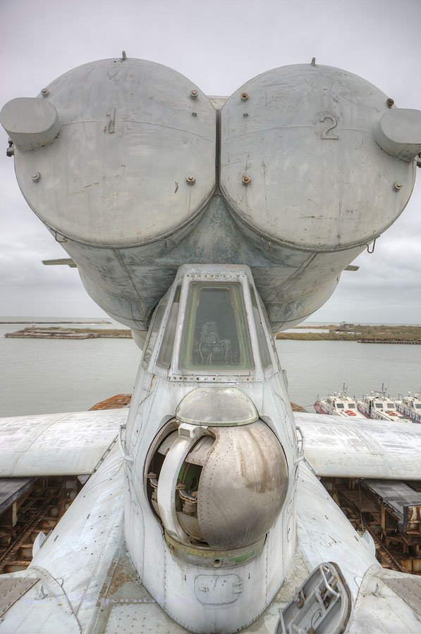
I would not like to be sitting there when those missiles launch!
But what a view… and what a bizzare location for a manned gun turrent.
Sorry if it is a stupid question but why cant this be done?
sorry for the porr qualility i have done this on paint brush 😉
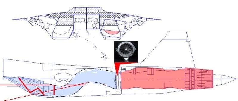
People that drawing has been shown to be incorrect in regards to the location of the main wheel undercarriage.
The mainwheel is almost vertical and stowed mostly within the side of the intake duct.
Sorry but my line drawings are a bit primitive…
When you look at the forward view below i put in (very roughly obviously) where the main gear sits (LH side) as well as the intake wall… also the inner intake has clearly shown some sort of buldge (variable intake ramp perhaps)
When looking from underneath the red lines roughly where the wheel well wall would sit.
Again one would imagine that only a very small amount (in the worst case) of the compressor face is visible. Though im doubting that Suchoi would spent all this money and not have a nicely hidden front fan!
Forgetting everything else….
But the long nose of the aricraft would essentially block the view of the compressor face if it was “visible”….. (following the red line)

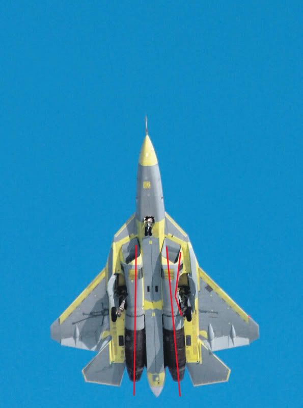
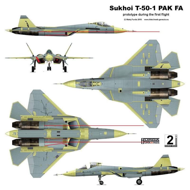
Question about the engine toe in…
We can see that the engines are toed in slighty at the front
(lord knows how it will compensate on one engine?)
Could it be designed this way in order to help reduce radar returns somewhat as head on both engines wont be at perfect right angles?
Even though clearly if the intakes contain no baffling or “S” bends, that there is only going to be a minimal amount of compressor face showing…
Or could it be to reduce IR signature?
Surely though the angled tray meant they were for firing against ground targets?
How on earth could you aim them at other aircraft?
Ok you had me there… I never knew the F-8 had a rocket pack.
Made me get out a few of my books.
I read one of my old books and it says the ventral rocket pack hinged downwards and that the air brake also deployed when it extended???
I can only assume that when the airbrake was extended , it was to help release the exhaust gases??
Now im interested to see any pics!
That last video is scarey indeed.
Shows how a “simple” rejected take-off/ heavy use of brakes on landing can turn into a real nightmare.
The firecrews dont seem to be responding well at all, except the poor hapless firefighter with the hose who several times can been seen asking for more water pressure!
No one appears to be throwing water on the right main gear !


 Sign In