I love these arguments.
Not one iota of information on the public domain on how these systems would fare against each other… But one and a half pages and we are already on industrial fisheries!
Can we stop the thread? There’s no available information in order to make any meaningful insight. The end.
:rolleyes:
https://twitter.com/US_Stratcom/status/1160218017957068800
for what its worth…
On the original topic:
1. Use a OTH radar to get early warning on incoming targets and their behavior. Here VLO techniques are ineffective.
2. Use long range high power arrays such as ballistic missile early warning type radars down to systems like the Resonanz. Brute force of their array will allow extended range detection against VLO targets but only if line of sight restrictions are respected. That means in practice, generally only high flying VLO objects can be detected at extended ranges.
3. Use conventional EW radars that operate at bands in which RAM and RAS can be neglected. For the rest, the shaping, brute force of a high power radar can be used. High ECCM capabilities are helpful as well as a multi-band system for signal analysis, to counter ECM and false target rejection
4. Use a ESA starring asset for high target update rate necessary to guide a SAM close enough for a kill. For the kill, an active radar seeker may be used, that is activated in the last 1-3km distance to the VLO target to allow a “burn trough” of shaping and RAM/RAS. Up until then the ESA starring radar would guide the SAM on command guidance into a “kill box”.
5. Use mature technology long range thermal cameras to assist the tracking of the target as well as false target rejection. Similarly have ESM systems for signal analysis and triangulation of the EM spectrum.
6. Use an Aerostat “balloon” mounted starring radar to cover low altitude and targets that make use of terrain masking. This restricts the tactical playground of airpower and protects the radar and SAM systems at extended range.
7. Use the starring high power radar assets for ABM purposes in order to protect static and larger components of the system against TBMs, MRBMs, IRBMs: OTH-B, ABM radar, Aerostat radar.
8. Use all available passive measures of sensor and guidance degradation: ECM, aerosol smoke screen, emitter decoys, relocation, GPS jamming, IR decoys, chaff, camouflage, thermal shielding etc.
9. Use short range missile air defense systems to protect the systems and AAA based air defense for expandable, low capability targets used for saturation.
Thanks! That case study gives good insight into the tools parameters.
I think we can be confident that the Gamma-DE has 3D beam forming capabilities to allow for sector-scan, starring mode, especially for ABM purpose (PESA 91N6E has it too by now). Observation modes are mentioned in the spec sheet further below. In that case the azimuth angle should be increased to >90°, right?
I would also like to know what would make sense for the “Fraction of time to search target” parameter. A portion of the aperture should be allocated to track beam functions, so what % parameter would make sense in this case? This is a main driving parameter which has dramatic impact on the results.
Another thing concerning the Gamma-DE is that photos without shroud show 560 elements at the 1 of 2 sub arrays. Based on this and your sub-tool for element count – frequency, I get 820 mhz. The paper says 1024 elements however, so could the rest be side-lobe cancelling elements or reserve ones?
Pulsewidth can be estimated from the range resolution which known to be 300 meters. Technical paper (which i would link below) about Gamma DE mentions compression ratio in excess of 100. Finding how much however is difficult. One way i sought is looking at AN/TPS-59 Radar as it seems Gamma DE have similar parameters.
The Pulsewidth is then can be “guessed” to be 1000 ms with 0.18 KHz (180 Hz) PRF. For 18% Duty cycle. The pulse compression ratio would then be 500 which appears reasonable with LFM (Linear Frequency Modulation) The LFM apparently the only pulse compression method where target velocity is not limited (Others like Polyphase etc are doppler sensitive and can only be used for target in Subsonic speed or less). The higher PRF and shorter pulsewidth could be exist too mainly to compensate for short range target detection. Transmitting at long pulsewidth and pulse compression solves resolution BUT not the minimum range.
So basically you selected the lower PRF number from the similar AN/TPS-59 to optimize the results for max. range – RCS performance. Pulsewidth came via duty cycle. But without that, what could we extract from the 300m range resolution and compression ratio of 100?
I would also like to know how much general practice those 20-40% safety reserves are? How do western and eastern radar schools handle this? Isn’t it redundant due to probability of detection parameter (just use e.g 95% to cover that margin)?
Fortunately you directly found the TRM power levels for this case, so we have become aware that there seems to be a 40% safety margin. Without that information, by using the tool to extract it, we would have got the wrong numbers.
The smaller 0.13 Sqm Yield range of about 301 Km or about 16% more than what is available in the export literature for the radar. This case would show overestimate of the sheet which might result from the limitation of the scenario (sector scan mode)
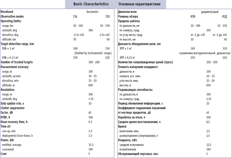
301km for a 0,13m² target would represent a 16% safety margin, yes. I wonder whether we can use that 250km number as fix point to vary unknown key performance parameters such as “Fraction of time to search target”.
This is a Technical paper by I.Immoreev regarding the design and development of Soviet/Russia ground based AESA. It contain good information on design and considerations about Gamma-DE Radar.
Thanks that was quite interesting. I wonder if the Gamma-S series uses that new (back in th mid 2000’s) TRM technology mentioned, with 200W instead of Gamma-DE’s 55W and where they are now with the S-band AESA for Nebo-M and beyond.
How about benchmarking the tool on some representative applications.
If range against a specific RCS is known as other parameters details like element power output could be calculated.
A example would be the Gamma-DE ground based L-band radar:
Element number and aperture size is known to determine operating band.
Range figures against two different RCS are also known.
Duty cycle can be approximated to get an idea about element power output.
If the numbers make sense, we can have increased confidence, specially if results make sense for some different applications (airborne, ground based early warning, ground based engagement radar)
Most interesting would be to see how Russians, Chinese, Europeans, Israelis and Americans are doing in regards to the technology for their elements (which can be extracted if element power output is known via the tool).
Just duty cycle must be approximated somehow to get reasonable numbers for PRF and pulsewidth. But that may be quite accurately possible if general TRM power levels are known.
The presentation of this deep upgrade as “new fighter” was a PR stunt.
Its the same Azarakhsh/Saeghe project of reverse engineering the F-5, but they have now reached a level of indigenous component production that it can be called “fully homemade”.
Its not the original F-5 anymore, the whole avionics has been modernized.
– Grifo radar copy with GMTI and SAR mode
– INS/GPS + TACAN navigation suite
– Modern HUD + MFDs with digital map
– Modern IFF, RWR, altimeter etc.
all on MIL-STD-1553 bus.
Full hydraulics and actuator suite
Plus a new ejection seat and J-85 small turbojet copy.
Previously they mainly had mastered the airframe, but could not do a serial production due to the lack of those critical subsystems.
Those interested can see the details in the video or this instagram site: https://www.instagram.com/iranian_defensive_power/
In total nothing fancy, but guys from the industry know what it takes to build all that from zero. The only OEM that would supply components to Iran is China… So kicking it off without foreign OEMs requires much effort.
Effort done for IR signature reduction. The engine ducts air after the fan stage to the rear, bypassing the afterburner. The special nozzle design suggests that this relative cold air is then used to reduce exhaust gas IR signature.
A little strange because the fan air temperature is about the same at the front as at the end (before potential afterburner). So for some reason IR reduction of potential afterburning flight would also taken special care of. Anyhow much emphasis on IR reduction seems to be made.
Talking about afterburner, I’m not even sure it has one. Maybe all emphasis is on an air mixing nozzle but why then take the fan air from so far at the front? Would the hot core heat up the fan air that much on its way trough the bypass duct?
The removal of the gearbox and integration into the internal one for a flatter profile is also emphasized. Flatness seems to be a positive feature after all.
@Austin
I discuss the number rpgtype7v posted here. I have serious doubts whether a 8-10 ton 11000km range single warhead ICBM could be possible but in light of a HGV like the Avantgard, my questions have arised.
Thanks for the article. Yes a HGV would make a PBV redundant.
I just wonder what range a 8 ton Rubezh, without PBV, and a single Avantgard HGV flying shallow (~150km) trajectory could have. If a full ICBM range of 8000-11000km would be possible it would be a revolutionary new miniaturized system.
A 8-10ton single warhead nuclear ICBM would be impressive. The Rubezh is now on hold.
HGV’s tested previously fly 2/3 of the range as normal ballistic missiles, with a range increase of about 20%. From the animation on the Avantgard we can see a almost non-ballistic HGV optimized flat trajectory.
I wonder if a 10 ton Rubezh which would have a range of 5500km on a ballistic trajectory would be able to reach a credible 8000-10000km ICBM range with an advanced HGV like the Avantgard. Heat management, continuous power supply for control surface actuators are all problems that would need to be solved if the Avantgard would fly a flat trajectory at ~150km altitude.
Another point is: Avantgard on Sarmat ICBM would normally have a higher release speed after boost phase that would make a much improved heat shield necessary compared to the lower velocity Rubezh.
So either the Avantgard on Sarmat is much improved regarding the heat shield or the Avantgard load is of a quantity/weight that slows it down to Rubezh burnout speed at release.
What makes me wonder is whether it would be possible to achieve 10000km range with a flat trajectory HGV, whereas a pure ballistic system would only do 5500km (Rubezh). Means transforming energy to create lift primary instead of transforming speed into heat as in conventional reentry vehicles. But would a range increase of up to 100% be possible?
– Data-linked PESA radar for airspace surveillance
– Hit and run capable with near mach 3 “sustainable” speed
– Real BVR capabilities for the 80’s
– and of course the simultaneous long range engagements, at least forcing jettison of weapons to evade –> aborted mission, if we assume a low PK for the R-33.
These are the unique added capabilities of the Mig-31 for the air force, more so for a large country. Having covered the A2A field with one dedicated asset with a secondary multirole, is it worth for me.
I would stick to Soviet gear and replace the F/A-18 (better would be F/A-18L) with the Mig-29 with its huge WVR (9g, R-73) performance for the 80’s. But its inferior A2G capability, shorter legs, fewer weapon options, makes the F/A-18 the better choice for bombing.
Twin engine is a must for me, otherwise F-16 (Sidewinder-only…) or Mirage 2000 would be also options for the low component.
Sure is that Soviets would have never sold the Mig-31 to an airforce that would be given the F/A-18 by the Americans.
Mig-31 + F-18
Altough unlikely to have been sold in that combo.
@stealthflanker
Thanks, yes I also found those data from radartutorial to model my VHF and S-band radars with you spreadsheet.
For the PW of VHF-band radars it seems to have been greatly increased in state of the art radars. Phase shift keyed signals are claimed to be 42*6µs for this P-18 upgrade: http://www.litak-tak.eu/en/products/radars/p-18ml/
If I have interpreted it right it would result into an effective 252µs pulsewidth. Hence the performance of an AESA solid state P-18 would be more than double for the same peak power (speaking of Nebo).
Then also the huge possible pulsewidth of 800µs for the AN/FPS-117 creates some confusion. But for low PRF it should be possible at max. duty cycle.
@mig-31bm
Jamming is not included, but the very high performance of large S-band arrays would not only be effective against VLO targets, but also increase the burn trough performance when jammed. Hence the range performance is a direct indicator for counter-VLO and (non-ECCM) counter-jamming performance.
You and stealthflanker are of course right about the array size. It is about 3,6m x 3,6m for 4000 TRMs and just 1600 for a 2m x 2m array.
However even those “just” 1600 S-band low power 50W elements would have a ~230km detection range against a 0,001m² target. This could easily mean that a VLO asset with a X-band performance of 0,0001m² would be detected at 230km stand-off range by that 2m x 2m array, in case the RAM/RAS (or also shaping) performance is decreased by 10dbsm @ 3Ghz.
I’m surprised by those performance levels. To some extend it changes the view that L-, UHF-, and VHF-band assets are the best approaches for counter-stealth. Use brute force of a cheaper TRM technology (non-GaN, 50W, possibly air cooled tile modules) and with a large enough array, you get the job done at a much higher position accuracy.
@swerve
Erieye-ER (one customer so far) has S-band GaN modules. I think the Erieye antenna is 8 x 0.6 metres, so about the same as your 2×2 metres. Dunno how many modules, though, or what power.
The GaN modules are said to give a massive increase in detection range of VLO objects. Maximum range against big, high RCS things such as ships is still the horizon.
I still have doubts about the high performance calculated by stealthflankers spreadsheet but if there is no mistake, it now makes perfect sense why some countries like Sweden go for S-band. Its not only economical but would have a high capability against LO up to VLO assets.
SiC, silicon and GaA are all able to provide a 50W peak power per element, no strict need for advanced and expensive GaN modules.
If there is no tight space restriction, a 6000 element array with low cost 50W elements provides the same range performance as a 3000 element, state of the art GaN 400W array.
Thanks to stealthflankers sheet, this now becomes visible. As well as the extreme performance even lower power 50W non-GaN S-band TRMs can develop, exceeding line of sight endo-atmospheric range against any conventional target and providing stand-off EW range counter-VLO capability or/and burn-trough capability in heavy jammed environment.
It now also makes sense why Russians skipped the Gamma-D radar and went for the Gamma-S, as its high power is sufficient to compensate better counter-VLO performance of L-band. On the other hand, you can’t achieve power levels of 50W without more expensive GaN modules in higher bands such a X-.
But I still don’t know if PW of 100µs and PRF of 2khz would be applicable for such early warning radars as those data are only derived from that TRM datasheet I posted. I still would like to know what PRF and PW levels are common for VHF- to X-band radars in search mode or illumination.
I would expect half wavelength spacing, hence a 2x2m array @ 4000 elements, which would be sufficiently compact also for airborne AEW purpose.
For such purposes it would also make sense to use lower power (~50W), non-GaN S-band modules, maybe even tile modules to drive the price down to <100$ levels.
For total costs, in a efficient design, the TRM cost could make up 50% ($400k) of the total radar production cost.
With all effects taken into account, an airborne array for an AEW platform would have huge range performance or very high anti-VLO performance. So high that it makes it a little suspicious.
Okay, so is it the maturity of advanced S-band silicon T/R modules that has created such high range performances?
The effects you mentioned should create negligible range performance penalty, am I right?
As a example: Such a S-band AESA in form of a ground based system like the Ground Master or an airborne AESA AWACS would have following performances with ~4000 modules:
50% Pd volume search: 300km against a -40dbsm target and that in 10cm S-band where RAM and RAS should be much lower performing. Means if we are generous and give a -10dbms RAM/RAS performance in S-band, its range performance would be in fact 300km against an effectively -30dbsm target (0,001m² RCS, shape only). That would be a typical long range EW radar range performance against almost any known stealth fighter target.
I’m somewhat skeptical about those figures. Maybe those pulse width and max. PRF values from the T/R module data sheet are for some reason not applicable?


 Sign In