Non-metallic nacelles will go a long way to reduce the RCS. Seems like there is extra metal across the middle of the fuselage. Probably integrated reinforcing structures to deal with bending loads?
High-temperature (up to 300°C) polymer matrix composites with a several mm integrated laminate of you know what.
I guess the addition of surface titanium panel reinforcements is more practical (and saves weight) as opposed to adding additional spars/bulkheads, which would also compromise fuel load. They’ll probably treat it with the spray-on version of the CNT RAM further down the line.
The ‘height’ of the reinforcements (plan view) is shorter compared to T-50-5 and the two protruding reinforcement strips running nearly the entire length of the upper fuselage spine, have disappeared. Surface finish appears a world apart from the previous static and the stretched canvass over the starboard cowling may indicate shaping for the inner beam aspect.
Actually, I just noticed the stretched canvass on the two cowlings are different shapes. The port is near circular and starboard is definitely not. Could it be the port is for the 117 and the starboard the definitive shape to house the Type 30?
This would be in line with the T-10M cowling shape and size differences with AL-31F & 117.
All bodes well me thinks. I berry heppy.
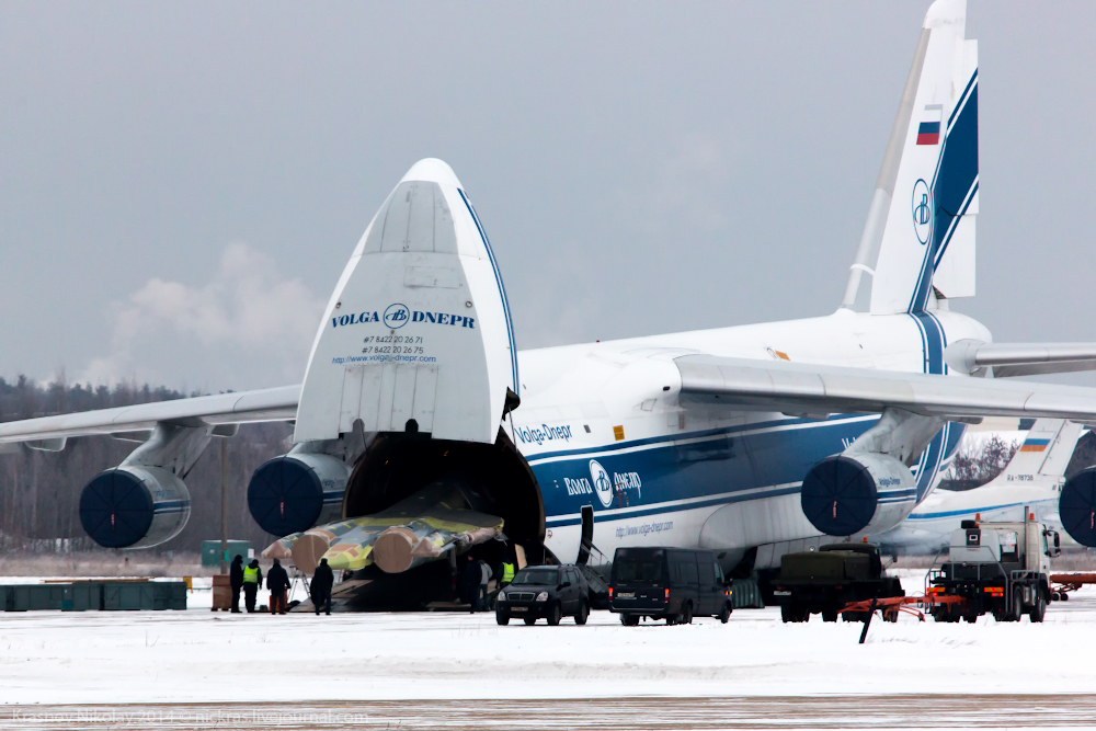
Static tester T-50-7 arrives @ LII (bye-bye metal cowlings)
C/o Господин Paralay.

Some great footage in this Sukhoi documentary- much of it company, new & behind-the-scenes (c/o Eldorado):
I don’t think it will be so simple. The diameter will probably be near identical, but the Type 30 will be shorter as it has 2 fewer HP compressor stages than the 117 and brand new materials with ‘clean sheet’ designs for the combustor and HP turbine, indicate more compact structures than the preceding generation.
This means the [S-]duct design may have to be slightly revised in shape and length with a recalibrated guide vane structure (downstream of the bend). Though I’d expect these ‘updates’ to be relatively straightforward.
Changes in Cg due to the Type 30 being significantly lighter will most likely be addressed by FCS software patches.
Ho-Ho-Ho, Tee-Hee!! Wishing a merry Christmas & happy, prosperous New Year to all fanboys & detractors of the PAK-FA!! …and also to those that fall in between (and even those extremists either side!!).
Regards,
JA.
A&D, the article states that a T-50 prototype will fly with the Type 30 in 2017. I find that hard to believe, note that UMPO has an order for 12 117 engines for the “second stage prototypes”, assuming 2 spares then this accounts for 5 upcoming machines- so T-50 mit Type 30 before 2018 is probably not likely. Even discounting spares, I don’t see 6 ‘stage 2’ prototypes getting airborne between 2015-17.
I do, however, think it will commence flight testing aboard a T-10M in 2017.
Do I think progress is slow? No. If you look @ the new materials & designs involved (including World firsts) such as [CNT]-Al LP comp., Ti-Al HP comp. (with 2 fewer stages than the 117), PMC shroud & stator vanes, a HP turbine blade described by it’s chief designer as “an absolutely unique product” and a brand new combustor- then it’s self-evident that such a radical departure from the 117 will take time stemming from inherent technical challenges and risks.
Remember, the lavishly funded and resourced AL-41F had a development cycle from 1982-92, so even if you factor that several of the Type 30’s elements were at the early stage of development in the second half of last decade (from both NPO Saturn and MMPP Salyut), then 2018 sounds about right.
Jō, has Sukhoi/UAC released any information about the sensor and data-fusion capabilities of the PAK-FA? In other words, can the PAK-FA achieve the same degree of data fusion and networking capabilities of the F-22A and F-35?
‘Integrated avionics suite‘ for the PAK-FA:
http://www.findpatent.ru/patent/248/2488775.html
…the T-50 will use a TKS-2 datalink, a Russian Link16 (also used on the Su-27)
PAK-FA’s data link is known as S-111:
Use GT for links.
The management’s plan was to turn RR into an ‘engine conglomerate’, this was only partially completed when the abysmal stock price performance (down 32% this year and falling) put paid to completing that vision.
By divesting it’s subsidiary holdings, the stock may regain as much as 20% and by spinning off the nuclear sub division, Rolls can rid itself of the government’s ‘Golden Share’ which blocks a foreign takeover of the aerospace division.
The winding down of the Trent XWB & 1000 development phase and the termination of the F-136 with no new major projects on the horizon will have shaken investor confidence. Cost-cutting by engineer lay-offs gave only temporary respite to shareholders last month…..but P&W and GE’s M&A departments will be rubbing their hands with glee!
But we aren’t talking about the F-35.
Little matters like tail volume ratio, wing t/c, wing a/c, wing aeroflexure and forebody separation characteristics contribute to stability margin over the AoA range as well as maneuverability…
Actually, due to the design *similarities* between the J-21 and F-35, the former is highly likely to be plagued by vortices’ induced buffet on the vertical stabilisers that effected the latter. When this problem afflicted the F-22 the scope for a design remedy was greater (structural changes to the fuselage forebody & inclusion of VGs).
However, for the F-35 due to the crucial design of the forebody for DSI interaction, this resulted in the unusual phenomenon of the inlet lip and wing LE vortices being pulled ‘inwards’ – hence the solution wasn’t so straight forward:

For very good [aerodynamic design] reasons, LM opted not to tinker with the vertical stabilisers’ design & location, instead choosing to increase their structural integrity.
Notwithstanding the issues of yaw control by moving them closer to the centre of mass, the limited options for a solution makes the arbitrary changes to the shape, surface area and location of the ‘J-31’s’ vertical stabilisers (albeit on a model) seem all the more ridiculous.
Also, your nitpicking over ‘trapezoidal wing’ terminology is pretty facile. You know exactly what I mean (i.e. NOT the moderately swept (42°) delta of the F-22 & T-50).
T-50-6-2 is the first flying prototype of the officially designated ‘T-50 prototypes of the second stage‘ (объектов ПАК ФА (Т-50) второго этапа).
T-50-7 is the static tester for these ‘second stage’ prototypes. So yes, T-50-6-2 will be close to production standard.
Logic would dictate that a new static tester for ‘second stage prototypes’ (and a gap of nearly 2 years from the first flight of T-50-5), would be strongly indicative of something other than:
…minute differences…
The wing produces more than enough lift at supersonic speeds. All wings do. Lift is not an issue, Cd0 is.
The thinner aerofoil will help reduce Cd0. But will hurt transonic (and maybe even supersonic) turn performance – LE and TE devices can offset this though.
Obviously, the most efficient wing design @ supersonic speeds would be an iteration of the delta- like the F-22, T-50 and J-20. The 3 versions of the F-35 have had sustained G limitations and transonic acceleration times increased as a direct result of differences in the trapezoidal wing designs. All 3 suffer from severe transonic roll-off & buffet @ different portions of the flight envelope.
The J-21’s marginally higher aspect ratio and thinner airfoil is not going to mitigate these inherent problems associated with the trapezoidal wing at both transonic and supersonic flight regimes.
LM investigated numerous vertical tail positions for the F-22 both fore/aft and inboard/outboard, eventually settling to where they are today. VLO, stability, control and buffeting all played a part in selection.
Yes they most certainly did. But did they do so without significant structural changes to the fuselage forebody and inclusion of VGs? – They most certainly did not!….but hey! We’re talking about the first (and only) prototype and a scale model- so let’s see how the design progresses from here on in.
Russian defence companies aren’t the only ones that like to employ creative marketing :P. They probably mean supersonic fighter in the loose sense that the fighter can go supersonic, but it seemed very apparent to me that the J-31 was not optimized for supercruise, and probably wasn’t spec’ed for it…
Maybe Shenyang’s marketing spiel should shift to something more specific like ‘stealth strike-fighter’.
Forward-fuselage shaping is a critical element for calibration of the DSI. If it later emerges that the J-21’s and F-35’s forward fuselages are dimensionally similar (and not only in appearance)- this cannot be a coincidence.
For example, a good indicator that the forebody of the J-20 is an ‘organic’ design is the appearance of the two vents on ‘2011’. The first is to deal with normal transonic shock and the second, low energy residual BL separation from the forward fuselage. Clearly, tools such as stereolithography and high-fidelity unsteady flow simulations were put to use here to modify a ‘ground-up’ design (though the design origins of the rest of the fuselage remain open to question).
This also begs the question that if the J-21 is being sold as a supersonic fighter, then why are they using contradictory design solutions? These include a fuselage forebody that is anathema to the transonic-area rule (like the F-35), it has a wing with marginally higher aspect ratio & much thinner airfoil (unlike the F-35). These design elements are contradictory- irrespective of engine thrust, the higher aspect ratio will not mitigate the lower lift of the thin airfoil and the efficiency of the airfoil that is optimised for supersonic performance will be undone by wave drag. Therein also arise the issues of aerodynamic efficiency to supercruise.
What appears to be arbitrary redesign and relocation of the vertical stabilisers in the new model @ Zhuhai, is like some afterthought. There are two major design considerations for the vertical tail arrangements. Both are relevant for high AoA and occur because of strong vortices which originate near the wing root-fuselage intersection or at the wing leading edge sweep change for some remain (neither of which appear to be modified in the new model). Such vortices cause high amplitude buffeting if the tails are too close to them at the most critical AoA.
Hence, the second design consideration comes into play: that for certain AoA and sideslip, one of these vortices impinging on a vertical tail can lead to forces which are in the wrong direction so there needs to be one tailfin which is upwind and completely clear of such wake interactions to guarantee the needed control authority over all AoA and sideslip.
It is important to note that if one takes all the non-US and non-Chinese 5G ‘organic’ M2 fighter designs and concepts (with & without foreign consultation) they don’t look like the J-21, or F-35 for that matter. So why has Shenyang come up with this half-baked, contradictory solution?
JMTs.
*
…AfaIk, only KRET and DARPA are serious about using nanophotonics.
Looks like they’re working on unifying radar, EW and ESM/ELINT & coms systems (English):
Sure, if you can provide any credible evidence stating that the exact material discussed in the patent has a RDP suitable for application at a 3 times greater depth than the test examples…
This scalability is a valid issue you raised earlier for which I had no (at least publically revealable) answer beforehand. However, that was then.
This Russian company (SKB ‘Electron’/СКБ “Электрон”) has demonstrated CNT RAM of similar (probably identical ‘recipes’), achieving -6 to -8dB absorption for 0.6 to 0.8 mm thickness:
http://www.vesti.ru/doc.html?id=1140846
http://youtu.be/vPXXVyy6raI. (from 02:00)
The NPO Saturn/Lyulka CNT RAM attains -15dB absorption for 1.5mm- so the evidence is clear: the absorption efficiency vis-à-vis material thickness is directly proportional and NOT logarithmic.
One issue with your source is that article includes a diagram stating the effectiveness of the material at the lower end of x-band is merely -7dB. LO aircraft with a 20 – 30dBsm advantage due to shaping + similar materials (all US and Chinese examples) are detected at 1/3rd – 1/5th the range.
This proportionality would mean for all of 5mm the absorption average is going to be in excess of -40dB, specifically for X-band ~ -28dB. I won’t patronise you with what a thickness of 1cm would mean.
Also, you need to note that the T-50’s cowlings are not true cylinders – they are flared, in fact for the region in question are much closer to what in geometric terminology are known as ‘ogives’. Added to that, a complex ogive would mean the worst offending beam aspect region will only be a certain segment of the cowling, but not the length and arc of the cowling in its entirety.
[ATTACH=CONFIG]233355[/ATTACH][ATTACH=CONFIG]233356[/ATTACH]
You can see for yourself that @ 9GHz and azimuth angle 90°, the measurement is around -15dB. As per NPO Saturn & Lyulka’s very own study into a metallic cone-cylinder model, the worst offending region is aspect/degree +/- 70° with 0dB (1m^2). Both these sources certainly contradict your insanely high baseline figure of 3m^2 (>5dB) akin to the average RCS of an untreated MiG-21 or F-18- just for the T-50’s side aspect!! This is a joke, right?!
[ATTACH=CONFIG]233357[/ATTACH][ATTACH=CONFIG]233358[/ATTACH]
Factor in the 5mm of their CNT RAM and it is self-evident from both tables above that F-35 stealth levels will be achieved. One cm will probably take them to near F-22 levels. Having said that, I do concede the pole model pic does indeed show a banked section joining with the cowling. This is most probably indicative of the “significant structural changes” to the upcoming ‘Stage 2’ prototypes.
Either way, the notion that the current T-50s’ design ‘flaws’ from yours (and others’) physical optics analyses will somehow not be addressed- is itself flawed and simply not tenable.
…and that 3 years of development of that exact material has increased its heat tolerance by 400%.
Oh, and I wouldn’t worry about high temperature composites, the document from where the RCS graph and pole model pics were taken is from Spring 2014, and it clearly states “high temperature polymeric materials”, notwithstanding such PMCs for in-service systems such as the ‘Bulava’ SLBM and ‘Angara’ SLV.
Not the powdered metal fuels (as these have been around for decades), but the efficiency of the new mechanical feeder system for the fluidised powder fuel (slurry). It increases the volume energy efficiency of the propulsion system by providing a more complete fuel combustion.


 Sign In