PAK-FA cannon and stealth housing patent:
A&D, No. Experimental components/stages of the Type 30 are expected to commence flight trials this year and a full-on prototype engine available next year*. Next to nothing is known of the FGFA’s definitive engine, and as concrete details are some way off -best refrain from speculation.
Djcross, informative as always and thanks for the ‘missing piece’ to the surge theory.
Haavarla, the latest buzz on the intertubes is swaying back to electrical power unit/cable fire (not directly engine related), my fingers are crossed for this outcome- otherwise the ‘engine surge theory’ could pose major design headaches.
the first article posted here said they were showcasing the bird for an Indian delegation.
They might have pushed the nbr up to impress the viewers or went in an unfavorable pocket of air.
But as you said it’s far frwd for an eng fire. They are talking about a surge and we know that the plane might have had BL ctrl problem (the vacuum piping btw the inlet and the compressor that was spotted on an early birds). So it might be a “simple” surge problem as stated by the article aggravated by the foam for the new composite material.
Anyhow, if true it confirms what we were guessing that, due to kinetic heating, the bird will be introduced in (at least) two phases : normal supersonic mode and, latter a faster bird that we all expect to see one day here.
Another theory relates to your CFD diagrams posted some time ago. the cause might be related to the injection point.
You and I Watson, deserve greater appreciation:
A surge from a turbofan engine is the result of instability of the engine’s operating cycle.*Compressor surge may be caused by engine deterioration, it may be the result of*ingestion of birds or ice, or it may be the final sound from a “severe engine damage” type*of failure. The operating cycle of the turbine engine consists*of intake, compression, ignition, and exhaust, which occur simultaneously in different*places in the engine. The part of the cycle susceptible to instability is the compression*phase.*
In a turbine engine, compression is accomplished aerodynamically as the air passes*through the stages of the compressor, rather than by confinement, as is the case in a*piston engine. The air flowing over the compressor airfoils can stall just as the air over*the wing of an airplane can. When this airfoil stall occurs, the passage of air through the*compressor becomes unstable and the compressor can no longer compress the incoming*air. The high-pressure air behind the stall further back in the engine escapes forward*through the compressor and out the inlet.*
This escape is sudden, rapid and often quite audible as a loud bang similar to an*explosion. Engine surge can be accompanied by visible flames forward out the inlet and*rearward out the tailpipe. Instruments may show high EGT and EPR or rotor speed*changes, but, in many stalls, the event is over so quickly that the instruments do not have*time to respond.
Once the air from within the engine escapes, the reason (reasons) for the instability may*self-correct and the compression process may re-establish itself. A single surge and*recovery will occur quite rapidly, usually within fractions of a second. Depending on the*reason for the cause of the compressor instability…
…and the reason for the compressor instability?, why the complex shape of the duct of course 😉 Also concurs with a number of engine fire ‘false’ cockpit alarms said to plague the T-50.
If the flames shot out the front of the 117, they would have burned the composite duct (as per witness statements), the location of the fire damage concurs with the complex shape of Asakurius Duckius:
Ladies & Gentlemen, there’s no need for C, Z, T or even O ducks, just short n’ sharp will suffice:
[ATTACH=CONFIG]226708[/ATTACH]
Note the LOS from intake mouth to engine placement is similar to that on the T-50. On the latter, the duct linking ‘Device 9’ and the comp. face will have a significant bend not only because of the statement “partially obscuring”, but also due to the comp. being canted downwards and inwards and ‘D9’ being installed “straight” [in the duct].
These screen grabs are taken from an official FGUP CIAM (ФГУП «ЦИАМ») publication dated 2012.
Pic 1 (below) is titled ‘Research Study of an Air Intake in Unsteady Conditions’, (up to M2.5). On the right are RANS renditions of surging & instantaneous velocity fields due to the convergent/divergent cross-sectional area of the intake mouth. One should note the striking similarities to the T-50’s intake*.
[ATTACH=CONFIG]226707[/ATTACH][ATTACH=CONFIG]226709[/ATTACH][ATTACH=CONFIG]226710[/ATTACH]
Pics 2 & 3 are concerned with shockwave & boundary layer interaction and flow separation, depicting the resultant velocity & pressure profiles. Take careful note Mr.MiG-29!!*
I think it is telling that certain charts & data tables have been deliberately obscured prior to publication and this study may well be related to the T-50. Including the rendition of the S-duct may have been a gaffe on their part- they’ve certainly revealed their design ideas. On 09/10/13 FGUP CIAM and NPO Saturn signed an agreement which included the “development of measures to reduce RCS” by means of “a net integration of the engine and the airframe”:
http://www.ciam.ru/?NewsId=1751&lang=RUS
I was thinking, as ‘short n’ sharp S-duck’ sounds clumsy, how’s about naming them ‘Asakura ducks’®- like some newly discovered species, [Asakurius duckius].
The Ukrainian armed forces combined are no match for this Lady:

All males (and probably many females) in the JSDF have already surrendered to her.

There’s no question of “re-engineering” the intake duct. They are a central, design-defining feature of all fighter designs, particularly 5G.
What most likely happened was that they utilised CFD code & algorithms to design the duct. However, when they opened up the envelope they found that the real-World data fell short of the predictions. I retract the comment “a step backwards”, what they’ve actually done is applied solutions to address these shortcomings, that they appear more fundamental than the F-35’s maybe an indicator of the differing requirements of the J-20, as well as the steep learning curve it represents for Chengdu et al.
So long as the engine-duct performance squares favourably with the aerodynamic/kinematic design and capabilities of the airframe (see Andraxxus’ posts on the other thread) and later engine upgrade, then they’ll have achieved their aim.
Someone suggested that this change could be meant to change the aspect ratio to increase the efficiency of the intake, but I half wonder if the change in the intake geometry has more to do with aerodynamic changes with the introduction of the slope on the top of the intake. I certainly don’t think capture area has changed significantly (but we’d have to get a good measurement of the capture areas of 2001/2 and 2011).
I’m don’t think we could say for that it’s a bleed system. After all if it does seem a bit of an odd place to put one.
Even if it were a bleed system I’m not certain we could conclude that it’s necessarily a step back, but that claim is a bit relative. Are they simply implementing a better system to get more performance out of the inlet at specific flight regimes (maybe push the plane’s supersonic performance?), or are they revising the design to something less efficient but can reach their requirements because the simpler design couldn’t?
Also, plawolf on SDF posted a theory about those vents. Would would be interested to hear your thoughts on it
“A little late to the party, but I think the hexagon meshes on the side of the intakes covers an intake and an exhaust which are used for boundary layer control inside the intake.
There would be sliding doors, which may or may not also be covered by a similar mesh screen, on the inside wall of the intake.
By opening and closing one or both of those doors, partially or fully, the J20’s intake would be able to create pressure fields that push the boundary lay airflow forwards or backwards when it first hit the outside wall of the intake, which would then feed through to affect where and when the shockwaves form inside the intake, which in turn determines at what speed the airflow hits the compressor blades.
Its a pretty ingenious design, which should allow the J20’s fixed DSI to achieve similar supersonic performance as traditional variable geometry intakes while retaining all the RCS advantages of the DSI. Its not a perfect solution, because the movable doors and mechanisms needed for them would surrender much of the weight and maintenance savings a basic first gen DSI would have over a variable geometry intake, but I think the supersonic performance gains are viewed as well worth the cost compared to a basic DSI.”
The first bleed vent (L) serves to strengthen the initial oblique shockwave, the second (R) is to deal with residual boundary layer separation due to the intensity of the initial shock wave (and ingested BL) downstream of the compression bump surface. The problem arises in the supersonic regime when total pressure flow is degraded due to the interaction of the bleed system and shock waves. However, as these two vents increase the bleed flow rate, then the severity of these low pressure gradients is reduced.
The F-35 also suffered from similar problems but LM instigated (at least one) redesign of the duct itself. Even so it is probable that the duct design will still, to some extent, inhibit the F-35’s performance. If Mr. PLAwolf is trying to sell these J-20 duct modifications as some sort of highly evolved hybrid of the DSI, he’s most welcome to- but his assertions would be wrong. After all the whole idea of the DSI is a simple, elegant high pressure shock solution devoid of mechanisms and gizmos.
The passive porous elements (above) employed on the JF-17 are almost certainly due to address the flow separation imparted from the forward fuselage, remember the DSI was retrofitted. One would need very accurate dimensional data on the J-20 before one can confirm the root cause of it’s DSI problems, but I would suggest they are for similar reasons- namely in the absence of a ‘conventional’ splitter plate and BL cavity, the design and dimensions of the fuselage forebody are not conducive to a pressure gradient that efficiently deals with flow separation, not only trans & supersonic, but @ various AoA.
I would say BL bleeding vent. Location is interesting…
Then they must be having problems with the DSI. The F-35 doesn’t have a bleed system, not even a passive bleed system incorporated into the ‘bump’ itself (see porous elements on JF-17 below), this may have limited benefits for the subsonic regime but performance will degrade significantly in the supersonic.

Besides, interaction of a DSI shockwave and bleed system will result in significant flow distortion, particularly in the S-duck.
It has the opposite effect of what conventional splitter-plate diverter type fixed inlets at supersonic speeds, where the passive bleed system on the splitter plate offers significant benefits by stabilising the downstream (after-terminal-shockwave) boundary layer.
Having said that, they may be attempting to increase the bleed mass flow rate to improve the intakes’ characteristics in both sub & supersonic regimes. It certainly appears the intake has undergone a redesign which would imply it was a problem area for increased drag. This is a common problem with DSIs.
Eitherway, it definitely looks like a step backwards.
Few things I found funny in your post though.
a) you were touting an amazing 5m accuracy which was merely the range accuracy that was listed on the sign. Basically simple pulse doppler range detection.
b) the important angular accuracy is 0.5 degrees. IE a target could be as far as 10km left or right of where the radar thinks it is, bit different to 5m right, about 2000 times different in fact.[i] This beamwidth/angular accuracy spec is what I debunked you on in regards to suggesting low band radar is viable on the small aperture of the Mig-31. That and gain which is calculated by G = ρ(4πA/λ2) where p is aperture efficiency, A is area. I’m sure I don’t have to point out the relationship of longer wavelength vs smaller area right?[ii]
[i]. http://army-news.ru/2010/09/raketnyj-kompleks/ (30 угловых минут)
[ii]. http://forum.keypublishing.com/attachment.php?attachmentid=225095&d=1386704433

Amiga, you know full well I mean adverse pressure gradient and in what context, but for want of getting into very heavy fluid mechanics theory here, I’ll leave it there. We can discuss it in PMs if you like.
MiG-29, I get the feeling you’ve totally misunderstood my posts, that may be due to a language barrier. However, that’s not important because you don’t have the faintest idea of what you’re talking about and your comments on this topic are embarrassing to read (no offence but seriously).
Yeah, you’re right TR1:
http://new.militarynews.ru/story.asp?rid=1&nid=331618
However, I think it’s safe to assume that this “fully digital AESA” is definitely a close cousin of the system destined for the S-500- a hidden gem that went largely unnoticed @MAKS2013, as I’ll elaborate.
I don’t have accurate data for Nebo-M but Nebo-SVU* has a Max detection range for a 2.5m^2 target of 360km with an accuracy of 100m. Even if you took the ‘M’ to be a 50% improvement it still falls way short of ‘Demonstrator’.
It significantly outperforms Nebo and the known parameters for the current S-400 systems. I’ve rechecked the translation for the advertising placard and can confirm it states “P-band; detection range Max 1,500km; automatic target tracking/lock on (95% probability for 1m^2 targets) 600km and get this: accuracy of 5m(!!) that’s <1/3 fuselage length of a Rafale; minimum targets tracked 25. It’s target tracking range is twice the detection range of the ‘Gamma-DE (67N6E) for a similar sized target, and ‘Demonstrator’ appears to have a smaller array.
As there’s no way Si-LDMOS or bistatic transistors could deliver that range, and resolution/accuracy for that sized array it can only mean GaN.
[ATTACH=CONFIG]225434[/ATTACH][ATTACH=CONFIG]225435[/ATTACH][ATTACH=CONFIG]225436[/ATTACH]
FD, the camo net’s to hide the T/R modules’ and number. I guess yours truly was also right about the significantly different arrangement & dimensions compared to Nebo. I think given the circumstances the reader can forgive my momentary hubris:
And Jo…
I would suggest you go pick up a radar or em theory manual or two before posting again. Can I suggest you seek some education on what happens when you mix small antenna area and width with long wavelength? The power source wasn’t the area where you went full retard on this comment. And don’t just be all sciolistic and just glance over a few buzzwords as you try (unsuccessfully) to do, actually try to grasp the concepts.
‘Who’s laughin’ now, Momma!!?
I wonder why people always talk about F22 and T-50 intakes always ignore F35, B2, J20 intakes.
Ermmm…..Precisely because of what’s written in that scientific NATO study (which you didn’t read or understand).
You’re a waste of time, this conversation is over.
B_I_O, it’s not just about “seeing further”, it’s EA/jammer functionality, multiple agile beam control, SAR and power efficiency. Most probably it entails a central processor upgrade too. If memory serves around 10 aircraft have been upgraded thus far. Not just PAK-FA exclusives I deliver, huh? 😎
..Why does the GaN program for the Apg-77 not exist? Simply because it isnt required..the supremecy of the F-22 is not challenged or will not be challeneged for quite a bit of time. Air warfare prospects for the US hardly call for an investment into GaN aesa for the F-22. I can understand the “want” to be ahead of the cutting edge in russia but money gets alloted (or should be) to areas where it is required..
But they do have a GaN upgrade programme for the AN/APG-77! It’s very low rate and commenced around 2010.
I can’t give you a source because all the material has been recently removed, but it came from the same document that detailed this development for Russkie GaN MMIC developments specifically for AESA T/R modules:
http://forum.keypublishing.com/attachment.php?attachmentid=225094&d=1391204901
In the T-50’s intake duct, both the supersonic and subsonic diffusers’ oblique shock waves will be susceptible to [boundary layer] flow separation (including secondary flows) to the normal of the wave. Here one can see the shock wave (in pink) and perpendicular flow separation (in blue & turquoise) for transonic flow in a convergent-divergent duct:
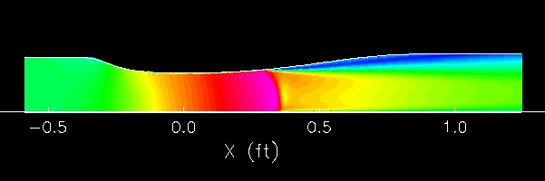
[ATTACH=CONFIG]225367[/ATTACH][ATTACH=CONFIG]225366[/ATTACH]
These turbulent conditions are significantly more pronounced for subsonic flow around an obstruction due to the adverse pressure gradient and will be further compounded in the T-50’s duct because it is short and sloped (label ‘5’ in the patent pic*), but also because of the variation in cross-sectional (highly convergent-divergent) area of the duct- as can be seen in the underside pic.
Hence, the adverse pressure gradient will result in particularly severe flow separation around the curve of the inner bulge where the MLG wheel stows. This inner bulge is an integral part of the subsonic diffuser.
Pic below demonstrates such [subsonic] conditions in a straight duct, the bulge may be steeper, but is certainly shorter compared to the T-50’s ‘wheel bulge’, but the effect will be similar:
[ATTACH=CONFIG]225368[/ATTACH][ATTACH=CONFIG]225369[/ATTACH]
Bear in mind an efficient inlet duct should be able to deliver uniform and high pressure-recovery flow to the engine face, then one can imagine the sum total of super, trans & subsonic shock wave flow separation and their associated pressure fields in the T-50’s duct, will deliver nothing of the sort. This is where Sukhoi and TsAGI designers have done their overtime with ANSYS ‘Fluent’ and supercomputers.
Then I came across a very interesting CFD study which I believe holds the key to what they achieved.** Basically, they designed a downstream ‘outlet guide vane’ structure whose vane geometry “is modified to exactly match the resulting inclined static pressure field” and hence neutralise/mitigate the effects of the turbulent flow across all flight regimes. The net result is to ensure the uniform and high pressure recovery to the compressor face.
In layman’s terms, the following is what the ‘OGV’ achieves (turbulent flow in orange, bend not to be taken literally):

One should note that this ‘OGV’ theory is entirely consistent with the anomalous angle/cant of the 117 compared to that ‘thing’ in the intake, scale and what appear to be secondary vanes. It’s also consistent with the official patent description of [Device 9] being “axially offset” from the engine’s comp.
Evidently ‘D9’ is dual function and becomes a stealth screen when they make it out of CNT modified PMC. It is part of an integrated engine-duct stealth solution. JMTs.
* http://www.findpatent.ru/patent/247/2472956.html
** http://forum.keypublishing.com/showthread.php?126959-The-PAK-FA-News-Pics-amp-Debate-Thread-XXIV&p=2111127#post2111127
Vnomad, so US 6G can have a RAS for a duct, but the T-50’s PMC duct can’t, not absurd much?
Berkut, do you remember that official UAC link describing the capital tooling for PAK-FA’s PMC RAS and coatings? Or did I dream that up? I won’t repost it ’cause you obviously didn’t read it, nor did you appreciate it. Very sad :(….
…or maybe you just didn’t understand it 😉


 Sign In