Relevant words from Chapter 3 of Haynes Manual. Strongly suggest you buy a copy Hugh, as I have old aeroplane habit that needs funding!! :diablo:
…….
FUSELAGE
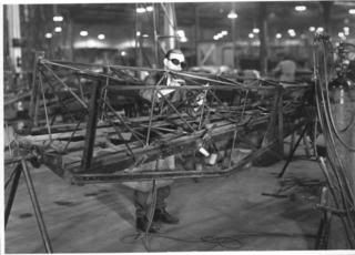
The main fuselage frame is constructed in three sections, using various gauges of mainly 7/8″ (22.2 mm) round and 7/8″ square section T45 low-carbon steel tube, which is welded to form individual rigid structures, which are bolted together. The engine mounts, forward fuselage and rear fuselage can therefore be replaced individually to speed repairs.
The core of the airframe is the forward fuselage, to which the engine, centre section struts, lower wing mountings, undercarriage and rear fuselage are bolted. It also makes up the cockpit area, with the wooden floor, seats and ‘control box’ containing the linkages for all the primary aircraft controls, being bolted to the structure.
The two main parts of the forward fuselage are the side frames which when assembled to cross members form the parallel sides of a box structure 7 feet 2 inches (2.18m) long.
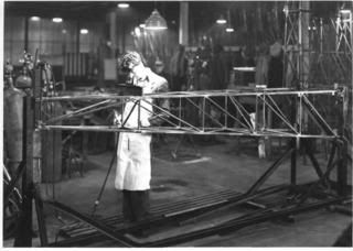
The front of each side frame is raked backward to reflect the slope of the non-structural aluminium engine firewall, while the top longerons provide the mounting points for the steel centre-section struts supporting the upper wings.
The two side frames are separated by steel tube cross-members and two 8 mm diameter steel tie rods. These tubes brace the floor, being bolted via flanged end fittings to the lower longerons at the point where the downward tubes coincide, to provide attachment areas for the root ends of the lower wings.
The forward points of the lower side frames also take vertical loads from the undercarriage, act as a mounting for the oil tank and the front of each side frame also bolts to two triangulated square section tubular frames which form the engine mounts at the front of the airframe. The engine mounts extend three feet (0.91m) ahead of the bulkhead on each side of the aeroplane and contain four receptacles for rubber engine mountings, two on each side, which correspond to the cast alloy ‘feet’ attached to the crankcase of the Gipsy Major engine.
The complete forward fuselage ‘cage’ is completed at the front and rear by upper and lower cross members and diagonal bracing, to provide a surprisingly light and rigid unit. To this, a total of 40, 2BA bolts and nuts secure the plywood floor, to which in turn is fixed the control box which forms a central spine at the base of the cockpits, upon which the seats are bolted with the occupants’ feet placed on each side.
The spruce and plywood control box acts as a single mounting point for all the primary flight controls and is removable as a unit for repairs or maintenance. The front and rear control columns are linked by a torque tube and a connecting rod which run the length of the control box, through both cockpits.
For the elevator control, a cross shaft with integral levers immediately behind the rear seat is operated by a short pushrod from the rear control column and is connected directly to the control cables running to the tail of the aircraft. A downward-projecting lever on the torque tube between the two columns operates the aileron cables externally, under the cockpit floor. The rudder controls too, are mounted on the control box and are coupled by connecting rods. The ends of the rear rudder bar extend out of each side of the cockpit and the external control cables run direct to ‘horns’ on each side of the rudder.
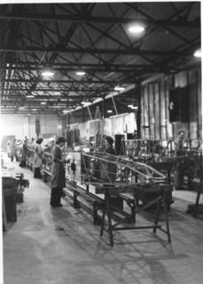
The rear section of fuselage is likewise made up of four 7/8″ (22.2 mm) square T45 steel tube longerons which taper through five reinforced bays to a single sternpost at the rear. Built on a jig as a single, rigid, 11-foot (3.35m) welded-up unit, it is designed to be simply bolted in place on the rear of the sideframes and already carries the drillings for the wooden top decking and the mountings for the tail surfaces……


 Sign In