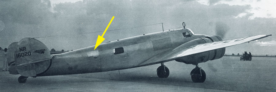
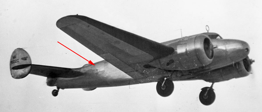
I’m having a bit of a problem reconciling the size of the rear window in the graphics (that was plated over), with the actual size of the rearmost window in the attached photo; looking at the size of the patch it would appear to be somewhat larger than the aperture it covers, in which case it is probably riveted directly onto the skin .
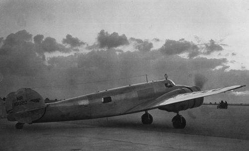
Stuart, this photo is prior to the extra large window being fitted into the rear toilet compartment, the window you see is a standard Electra passenger window that has been left in place opposite the passenger door (where as the others were deleted forward of that location and on the opposite site where the fuselage fuel tank vents are fitted.
The Window, and the later patch, are both “after market” modifications.
Regards
Mark Pilkington
There is a point where, in the name of playing devil’s advocate, you end up doing TIGHAR’s work for them.
I am open to being convinced, but am sceptical that this artefact is the patch, or that the Lockheed and Earhart made it onto Gardiner Island.
If reviewing their claims I become more convinced, good luck to them, (of course the ALCLAD Stencil seems the Achilles Heel to their theory but I am willing to set that aside at this time and test the logic of the rest of their arguments and evidence.
Any ‘analysis’ that involves drawing lines in MS Paint over a photograph is not analysis.
Smiles, then overt your eyes NOW! LOL
TIGHAR are not qualified for any real analysis, and frankly the work in this thread is probably of a higher standard.
Well to be fair, what I have been doing above is simply reviewing their analysis and coming to different conclusions, other than the independently provided (NTSB Report) dimensions of the Artefact, and the Lockheed station points for the main fuselage frames, everything else we have access to is via the Tighar Filter.
(As identified from their own tape-measured photo above, the patch is considered to be 17″ from bottom rivet line to top rivet line, yet the NTSB Report into the Artefact states:”The sheet was a comparatively large piece (23 inch x 19 inch) of 0.032 inch thick aluminium alloy” http://tighar.org/Projects/Earhart/Archives/Documents/NTSB_Report/ntsbreport.html ie its 2″ too big – due to that tab at the bottom!)
But there does seem to be some errors in their logic for the rivet lines of the window and therefore the patch, which then “accommodates” the artefacts dimensions, however if my own “analysis” drawing lines in MS Paint accounts for the inner spacing of the window frame rivet lines being re-used for the patch, and then also allowing for the lower tag of the Artefact, you end up moving the artefact aft and up to get it into the front and lower rivet lines.
“IF” that assumption is correct, the artefact then compromises the aft and upper rivet lines of the patch?
When it is all said and done, why is it that only the DIY toilet window cover would survive from Amelia’s aircraft? Why that bit? Why nothing else?
To be fair, Tighar now claim an anomaly in the previous sonar has been “re-assessed and is more than likely to be the fuselage, and want $3M to go and have a look!
And Tim Mellon a former $1M sponsor of the last expedition has already “identified” much of the aircraft sitting on the reef floor as far as he is concerned, and that was the basis of his law suit against Tighar.
Poor Tighar they just cant win, we luddites disbelieve their claims of evidence of the Lockheed ever being at Gardiner, and accuse them of embellishing their claims, whereas a true believer and sponsor accuses them of hiding evidence that proves the Lockheed is definitely there!
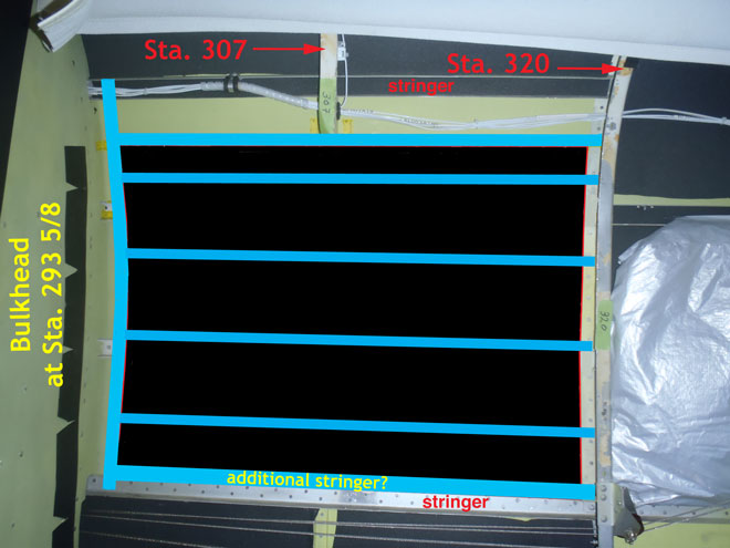
So here is my Fools Errand! in living colour – done in MS Paint over their photos! of course the same real analysis could be done with a tape measure if you had access to the artefact and the New England Electra at the same time as Tighar did, yet didn’t apparently identify this issue? (or did they??)
Fools Errand 1 – remove the artefact.
Fools Errand 2 – red lines to represent the rivet lines of the patch, as per the referenced window frame picture and the Darwin Patch photo.
Fools Errand 3- Reposition the artefact to fall in line with the forward and lower rivet lines.
Result? the Artefact compromises the rear and upper rivet line boundaries of the Patch?
(ie the 2″ at the top is caused by a 19″ high Artefact fitting against a 17″ high patch?)
Regards
Mark Pilkington
Its an interesting aspect to consider, if the patch is not extending the full length between frames 293-3/4 and 320 then there is less than 27″ to the length of the patch, while the remaining section of the Artefact is 23″ long, leaving less than 4″ to be missing?
Indeed the smoking gun with the “?” is well worth remembering at this time, as there seems to be many un-answered questions in this hypothesis.
I’m still not convinced there is any correlation at all between the 5 rivet lines on the artefact and any such lines on the patch? or that the 5/32″ rivet line and tag at the bottom of the Artefact are explainable against the known elements of the patch and double row rivet line in the original structure and the window frame?
The only alignment so far is that the artefact seems smaller than the patch, but even that is getting tight?
regards
Mark Pilkington
the Tighar forum seems to be honing in on these same issues?
http://tighar.org/smf/index.php/topic,1490.900.html
Re: 2-2-V-1 – patch?
« Reply #914 on: November 05, 2014, 02:48:14 PM »
Greg DaspitRegarding the tape on the plane.
Is Mr. Glickman using it to determine and match scales of different photos at known points close to where the patch may be or is it meant to define some limits of the patch?
If the tape is defining limits of the patch then which edges of the tape define it?
* Tape question.pdf (120.35 kB – downloaded 51 times.)
Greg
TIGHAR #3971R
Re: 2-2-V-1 – patch?
« Reply #915 on: November 05, 2014, 04:58:40 PM »
Ric Gillespie
Executive Director
Administrator
“Close to” is the best we can do. There isn’t enough resolution in the photos to see precisely where the edges of the patch were. In the selfie with Nilla Putnam we can see clearly where the window frame was attached and there must have been structure added for the frame to be riveted to. Logically the patch was riveted to those same structures but trying to pin down exactly where the patch edges were riveted is a fool’s errand.
Its not that difficult to pin it down exactly is it?
There seems plenty of good quality photos of the window frame that confirms its located within the positions of 293-5/8 & 370 and surely its possible to scale of one of those photos to determine the forward and aft rivet lines of the window frame and therefore the patch – even if the patch extended fractionally beyond the rivet lines that doesn’t impact on the comparison with the horizontal width of the Artefact?
The same is true of the vertical height of the window/patch rivet lines?, and the Artefact?
The Darwin photo seems to convincingly confirm the patch edges and rivet lines are based on the window frame, not the original Station Frames at 293-5/8& 370.
http://tighar.org/smf/index.php?action=dlattach;topic=717.0;attach=2721
Tighar “seems” to acknowledge that issue themselves on the internal photos? taken at New England?, so why is the tape on the Frame 293-5/8 line?
So the $64 question is, what are the apparent dimensions of the rivet line perimeters of the window, as compared to the Artefact?
“Logically the patch was riveted to those same structures but trying to pin down exactly where the patch edges were riveted is a fool’s errand.”
But no more a “fool’s errand” than any other hypothesis being tested by Tighar? (say like like Faecal DNA and Turtle Finger bones?)
“Questions are EASY, Answers Less So”
Regards
Mark Pilkington
Actually despite all the detailed analysis Mark I suspect that the deal killer is the absence of that double line of staggered rivet holes on the small piece of the artifact that extends below the claimed line where the rest were supposedly torn off.
That’s my view too Malcolm, and was at the beginning of this review of their analysis. (on top of the “Alclad” issue)
Hence with the un-satisfactory explanation of the lower 5/32″ rivet line on the artefact and its alignment to the lower edge of the patch and its existing 5/32″ double rivet rows, at this time I seriously doubt that it is the patch.
The single row of 5/32″ holes along the lower torn edge of the Artefact, and then the 1″+ tab that then hangs lower still is the elephant in the room!
This doesn’t match the known staggered row of 5/32″ holes in the original airframe horizontal stringer or longeron that was used as the lower edge of the window and aligns with the lower edge of the patch.
If you “lift” the artefact “up” to “allow” for that double row configuration to be missing but below the tag, (ie torn off and lost) then you risk compromising the top dimension of the patch, and have a lot of trouble explaining the role of the existing row of single 5/32″ holes inclusive of the un-even spacing that then occurs near the tab?, given all the other intermediate rows are then 3/32″ holes?
This seems why Tighar then create the need of a 5th stiffener to sit along the top of the existing double row stringer, (without explaining why its there?/ for what useful purpose other than to fit their hypothesis?)
The only logical reason it would be installed is if you didn’t wish to disturb and use those existing 5/32″ holes to fasten the patch?
But the issue then is that this stiffener isn’t a stiffener, it would actually be holding the skin onto the aircraft, and would need to be tied into the frames either side of the patch.
But if you don’t use those existing staggered holes, then you would have to try and skin over them, and they are round or dome head rivets, and so your patch would bulge over them, and you would need to extend past them to rivet flush below them.
To hold that skin down over the dome rivet heads below it, would likely need 5/32″ on either side? perhaps justifying the single row and the 1″+ tab below it and likely another single row of 5/32″ riveted to the existing skin?
Yet the patch finishes, and is riveted along that existing stringer line, ie those staggered 5/32″ rivet holes are clearly used to fix the patch.
Once you accept that, there is no need or explanation for the new “5th” stiffener or another single row of 5/32″ rivets, (other than to justify the existence that row of holes on the artefact) and the “smoking gun?” starts looking much more like a “water pistol!”?
These issues are all visible on the artefact and the photos of the patch, there is no need to extend into “forensic analysis”, or even “false colour imaging” as Mr Glickman specialises in, looking for other rivet lines to match between the artefact and the patch, as we are having enough trouble matching the rivet line on the bottom between them both!
Regards
Mark Pilkington
Re: 2-2-V-1 – patch?
« Reply #860 on: October 31, 2014, 01:07:11 PM »
Ric Gillespie
Executive Director
Administrator
*
Show me where we claimed that it’s a smoking gun…….
Reading their forum again I found a link to this earlier Tighar Analysis webpage/report from Sept 9th, of the comparisons of the Artefact to the Patch.
http://tighar.org/Projects/Earhart/Archives/Research/Bulletins/72_SmokingGun/72_Smoking_Gun.html
Guess what’s in its URL and title?
tighar.org/Projects/Earhart/Archives/Research/Bulletins/72_SmokingGun/72_Smoking_Gun.html
Earhart Project Research Bulletin
September 9, 2014A Smoking Gun?
Artifact #2-2-V-1
Certainly more “asking the question” than making an announcement, but given Gillespie’s subsequent media statements its implied it is a “Smoking Gun”!
Of course I’m not the only one who is raising that issue, here is an interesting recent comment on their forum!
Re: 2-2-V-1 – patch?
« Reply #872 on: November 02, 2014, 01:55:01 AM »
Oskar Erich Heinrich Haberlandt
It’s important to see there’s no bulletin ‘A smoking gun’. But there’s a bulletin ‘A smoking gun?’, and that makes a great difference. Many newspapers (here in Europe too) don’t quote the “?”, and that makes it difficult for TIGHAR. Newspapers are careless, we all know, and they write what they want to write, and very often that`s (sorry) bull-s.
Oskar, 4421A
Yes – that “?” makes all the difference, and its the media’s fault for not including that element? of uncertainty? in their reporting of Tighars claims? smiles
So what does this research claim?
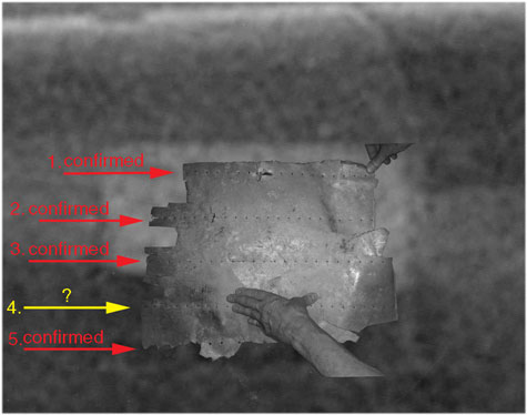
Does the rivet pattern match?
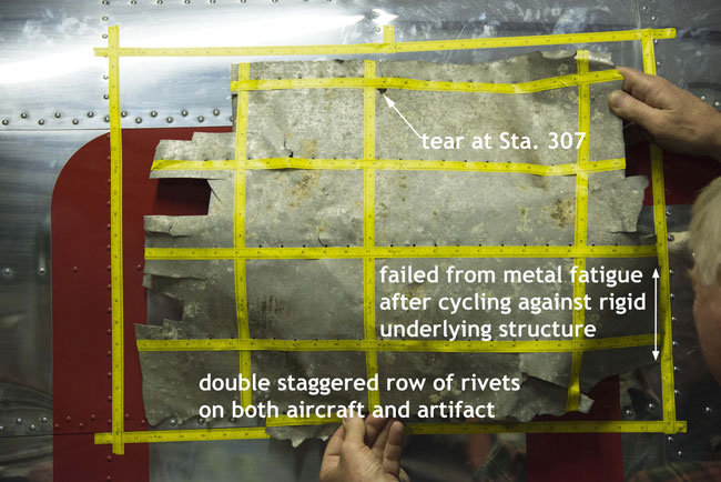
Yes, to the degree it can be determined at this time. So far, Jeff Glickman has been able to confirm that four of the five lines of rivet holes on the artifact match rivet lines that are detectable on the patch. The line of rivets that falls within the dark area on the patch may or may not be possible to find simply due to the lack of contrast. With an accurately scaled fit and a four-out-of-five match on the rivet pattern the probability that 2-2-V-1 is the Miami Patch approaches certainty.
The identification got an unexpected boost when Jeff Glickman noticed an indentation in the artifact that suggests the presence of a stiffener running vertically behind, but not riveted to, the metal sheet.
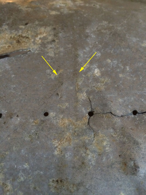
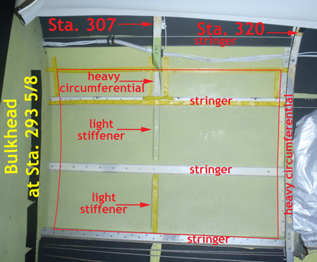
One edge of the artifact failed from metal fatigue after cycling back and forth against a rigid underlying structure. If the artifact is positioned in the overlay with that edge against the known underlying structure to which the window had been riveted, the implied vertical stiffener corresponds exactly with the standard Electra vertical stiffener at Fuselage Station 307.
This new correlation between the artifact and the Electra prompted further investigation that revealed a possible explanation for why the window was replaced.
The structure of the patch, as implied by the features visible on 2-2-V-1, re-connected stringers to restore longitudinal strength. Stiffeners were added to prevent “oil-canning” of the patch, and the vertical stiffener at Station 307 was re-installed to restore circumferential strength. The vertical stiffener was not riveted, possibly because there was no need, or perhaps they simply ran out of time.
As compelling as all this may seem, there is more we need to do before we draw any firm conclusions.
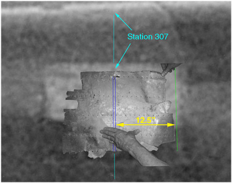
So the suggestion is, that the patch is marked with the imprint of the vertical frame at station 307?
Yet there seems to be plenty of photographic evidence that this vertical frame was removed at the time of the fitting of the special window?
The suggestion here is that the installation of the window and removal of the section of station 307 created structural weakness and the patch was installed to re-instate that structural integrity and so too was a replacement section of station 307.
YET?
Whlle there is time and effort to install 4 or 5 new horizontal stiffeners with lots of 3/32″ rivets, there is no time or interest to rivet to the new section of station 307 (apparently re-installed due to structural integrity concerns? – surely then there would be great need to rivet it to the “stressed skin”?, and certainly no loss in doing so?
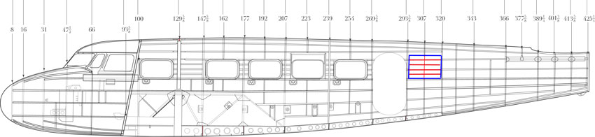
Interestingly, Glickman’s photo above shows that the imprint of this ‘frame 307’ is only 12.5″ from the edge of the Artefact, that would place the surviving edge of the artefact at station 294.5″ (ie 307″-12.5″ and ignoring the thickness of the frame at 307), yet that would now be within 0.875″ of the frame at 293-5/8″(293.625″) and not allowing for the fact that these frame stations should be “centres” not edges?
Therefore where is the room for the additional window vertical stringer they identify is needed to fit the window in the first place and to mount the front edge of the patch to?
Clearly something did exist in this location on the Artefact, but was not riveted into place on the skin, apparently instead having the stringers mounted to it, and the skin mounted onto the stringers, a rather complicated construction for a patch repair?, and again, why not insert some 5/32″ rivets into it through the skin to increase the strength?
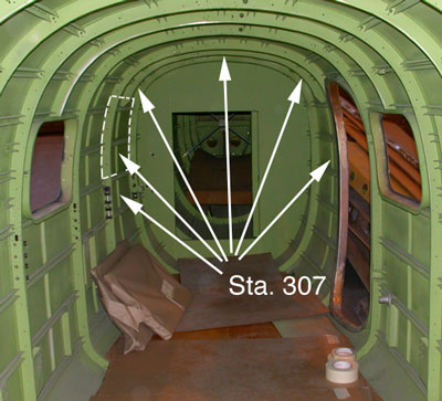
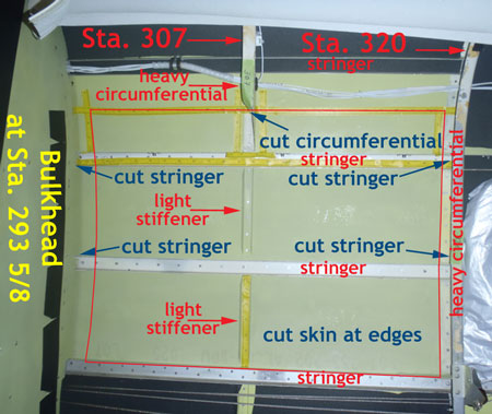
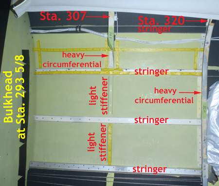
Interestingly, from their photo above, and Tighars later work with the New England Electra, we can see that Station 307 was not a full vertical folded frame in anycase, with apparently only light stiffeners existing in the vertical section where the window and later patch were fitted, and clearly riveted into place against the original external skin?
So “unless” the re-installation of a folded section at station 307 was undertaken behind the patch, (with perhaps countersunk rivets or angled brackets holding it to the horizontal stringers , how is it held into place without riveting it to the skin of the patch?
and why wouldn’t you rivet it to the skin of the patch if the reason for installing that frame and the patch was to re-instate structural integrity?
Clearly there “is” evidence of a frame or structure on the Artefact, but I’m not sure its presence helps the claim it is the patch?
More interesting is that the re-installation of the frame appears to get dropped from their hypothesis in their next “riveting” instalment, ie their step by step bulletin of October 28th?, it doesn’t seem to rate a mention? – why is that?
http://tighar.org/Projects/Earhart/Archives/Research/Bulletins/73_StepbyStep/73_Step_by_Step.html
Some of these same questions seem unanswered on their forum too
Re: 2-2-V-1 – patch?
« Reply #870 on: November 01, 2014, 03:39:56 PM »
Dave Thaker
I enjoyed reading ‘A Smoking Gun’ and seeing how Ric, Aris, and Jeff studied the Wichita Electra, but I am still not clear on some aspects of how 22v1 fits the jigsaw puzzle of AE’s Electra. Where does the bottom of the tab fit on the Fuselage of the Electra? It would seem to me that it would have to be below the double staggered rivets on the bottom of the frame of the navigator’s window, but on the other hand, I don’t see the tab in the Darwin photo, which seems to have sufficient resolution for it to be visible. Maybe the tab is actually the only surviving bit of the bottom of the patch?–but then what did the other line of 5/8th inch rivet holes seen on 22v1 attach to?–i maybe what is marked as ‘additional stringer?’ in one of the ‘Smoking Gun’ illustrations? Could someone clarify this point?Also, if the borders of the patch were the frame of the navigator’s window, then why in ‘Smoking Gun’ does the patch appear to extend to Station 320? The Darwin photo seems to show separation between station 320 and the window frame.
Its an interesting aspect to consider, if the patch is not extending the full length between frames 293-3/4 and 320 then there is less than 27″ to the length of the patch, while the remaining section of the Artefact is 23″ long, leaving less than 4″ to be missing?
Indeed the smoking gun with the “?” is well worth remembering at this time, as there seems to be many un-answered questions in this hypothesis.
I’m still not convinced there is any correlation at all between the 5 rivet lines on the artefact and any such lines on the patch? or that the 5/32″ rivet line and tag at the bottom of the Artefact are explainable against the known elements of the patch and double row rivet line in the original structure and the window frame?
The only alignment so far is that the artefact seems smaller than the patch, but even that is getting tight?
regards
Mark Pilkington
Hi YK
Many thanks for the link. We’ve previously been in touch with the dive team and unfortunately there is little likelihood of the local authorities there allowing any recovery of the aircraft, which is a crying shame.
Welcome to the Forum btw
John
Hello John
I assume the one in the youtube from YK is EF256? off the coast of France?
Any updates on the current status of EF311?
Do you know anything about LJ833 lost in a River Ditching in Germany in 1944 (I assume it was recovered?)
T/O Fairford on resupply mission to
Arnhem. A/c hit by flak and attacked
by fighters and caught fire and broke
up as it was ditched 16.00 hrs in the
River Maas at Demen near
Ravenstein. Sgt Smith, F/Sgt Orange
& Dvr Bloomfield got into the dingy
and wee helped to the riverbank by
some local men. The rest of the crew
including the other dispatcher from
253 (Airborne) Comp Coy RASC were
presumed to have drowned
or LJ925 lost into a lake in Norway in Feb 1945
and rumoured to survive as remains in 5M of mud, and was previously explored by the UK MoD?
Flying over Kristiansand aircraft was
intercepted by three German
nightfighters from Nacht Jagdstaffel
based at Kjevik Aerodrome which shot
up the starboard wing. After dropping
containers over Arendal the tail
gunner, navigator and bombardier
baled out of the aircraft. The aircraft
crashed into Holen Lake near
Arendal, Norway
NA672
lost in 1945 into the sea of Denmark, the crew survived?
T/O Tarrant Rushton 20:18 hrs on
SOE dropping mission TABLEJAM
353 to the Lolland area of Denmark.
Aircraft came down in sea just off
coast
These Stirling remains wont survive much longer (if indeed they are worth recovering even now?
but a set of Wings and Centre-Section remains would go along way to creating a viable reproduction if they could be recovered and put into a lemon juice hothouse? smiles
Probably too late and too expensive to see a Stirling recovery effort?
Regards
Mark Pilkington
It occurs to me that patching over a window doesn’t require stiffeners to be introduced, because the airframe has already been strengthened for the window; the C119 has numerous panelled over window apertures, all of them larger than the one on the Electra, and none of them stiffened, just a thicker gauge of metal.
I wondered that myself Stuart.
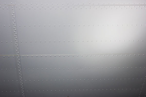
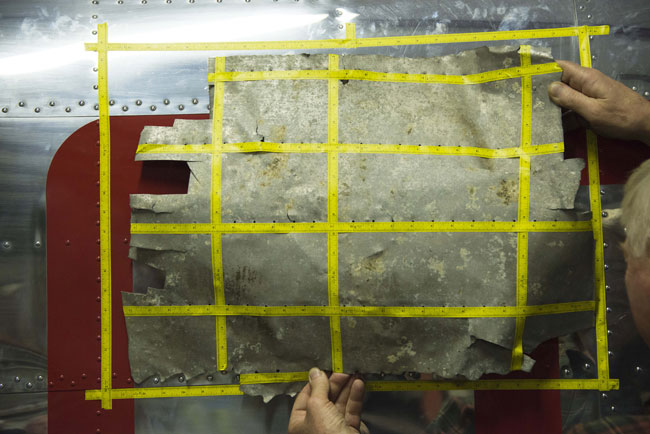
The image of the patch shown above, if available in a higher resolution scan, might disclose the stringer pattern rivet lines, – or the lack of any?
I remain surprised this image hasn’t been “forensically analysed” instead of the more blurry one they are promoting to the media, it seems much clearer, and of higher resolution, – I do wonder how big and good the original print is?
Regards
Mark Pilkington
My other issue with the whole TIGHAR premise is just where the piece was found; the island in question is (from memory) 400 miles from the island that Earhart and Noonan were trying to reach. Nobody disputes that they were running-out of fuel so why if they were unable to find their target island would the ‘logical’ thing be to head for an equally small, uninhibited island hundreds of miles away, that didn’t even have a runway? A course that also took them away from those trying to guide them into their target island and also the only source of ‘search and rescue’ for a thousand miles in any direction!
Oh, and if you were going to make such a dangerous decision…..wouldn’t you tell somebody by radio?
Well that’s the 64 Dollar Question.
Its clear Earhart was not receiving the voice replies from the ship, but apparently heard one morse code reply, and had no ability (or skill?) to converse in morse, or undertake a DF course setting on the morse signal?
Equally she didn’t apparently stay on the radio long enough for the ship to get a DF course setting from her transmissions, which even though she wouldn’t have heard their instructions to her as to where she was, would have allowed a much tighter search to be conducted to try and find her.
Apparantly Noonan’s navigating habit was to set a course offset from the target destination and then to turn into the destination, this would suggest they flew on a course slightly to the north of Howland Island, suffered the bad weather and had to fly at only 1000′ as they approached the location, turning south would have them flying with the sun behind them, allowing the island supposedly to be spotted easily.
Clearly they didn’t “fly over” Howland Island and the Ship, but were at one time close, the question is – did they continue flying south, or fly up and down the “line” from the point they initially reached flying east?
Did they travel that far south thinking Noonan’s navigation took them too far north (ending up at Gardiner Island), or alternatively did they fly north thinking the converse? (Mili Atoll here we come?)
If their last call is correct, they are flying the North – South line, not turning back to the Gilbert Islands and about to fly all the way to Rabaul without letting anyone know that’s where they are headed.
Subsequent calls suggest they might have seen “land ahead”, (Mili Attoll or Gardiner?) but there is no further calls advising they are making a forced landing on an island, and equally there is no mayday call that they are going into the open sea?
It does seem they were flying away from Howland Island, but in what direction? (north or south are the only two real options, I don’t support the return trip to the east)
Then there is the Pan Am triangulations of post crash radio calls, and the various suspicious calls heard in the US.
A great mystery!
Tighars Hypothesis is a reasonable one to test, but so far after 10? trips to the island, the skelton, the sextant box, the shoe, the cream bottle, the bits of aircraft skins, the turtle finger? and of course lets not forget the faecal samples (god how many natives, settlers and US servicemen must have crapped on that beach! over the years!) are not the “smoking gun”!
Neither is the blurry photo of the undercarriage leg poking out of the water but not attracting the interest of the photographer in the row boat?
Neither are the coral formations claimed to be bits of aeroplanes such as undercarriage legs!
So lets see how far this artefact 2-2-V-1 can get fitting and matching to the attributes of the patch! and what evidence Tighar can come up with to deal with the Alclad stencil?
Regards
Mark Pilkington
Thanks Mark but aren’t you ignoring that the marks on the piece suggest that it was made in or after 1943. In which case the question of rivet holes is a bit irrelevent 😀
Smiles, I guess I am willing to play Tighar’s game and put that “minor” issue to one side and deal with ALL the rest of their other claims of “matching” fingerprint/DNA between the Artefact and the patch.
Clearly the patch doesn’t appear to have ANY stencilling showing on it in anycase?, and either Alcoa is right, or they are wrong, (and I cant prove that in either direction), but am happy to accept Alcoa should know.
Until someone shows a production line photo of a pre-1938 (or pre 1941 for that matter!) aircraft being put together with sheeting showing the “Alclad” stencil, I think its Tighers problem to prove Alcoa wrong, “unless” enough conclusive photographic evidence of the patch can evidence matches on the rivet lines etc, so that the doubt that the artefact is the patch is removed (and to do that the resolution would probably also show the stencil in anycase).
They clearly dont have the conclusive photographic evidence?
But Tighar often works on the “if its not proven in the negative” then they will assume it falls to Tighars benefit, – this is why I consider the bottom edge tag and rivet line of the Artefact is so easy an issue to dispute the patch with, if they cant explain how that works – its clearly not the patch.
(unfortunately its always very difficult to prove a negative)
They have the artefact, they have the photos of a surviving Electra outside and in, and they have enough photos of the patch as I mentioned above to try and address that bottom edge tag and the 5/32″ row of holes?
I personally suspect the skin is from a aerofoil section of a wing or tailplane, with the 3/32″ rivet line for the intercostal /stringers, and the 5/32″ rivet line being from the spar, or a skin join.
The NTSB report notes this skin has dimpled rivet holes reflecting the skin being under stress, and its possible the slight curve of a flying surface, together with the effect of lift, might have achieved that?
ie it need not be a fuselage skin?
I note that the TIGHAR Commission workshop at the NMUSAF did not get up and crawl all over the flying surfaces of the aircraft and focused mainly on fuselage section examination.
http://tighar.org/Projects/Earhart/Archives/Research/Bulletins/71_RiddleOf22V1/71_Riddle22V1.html
Since its discovery on Nikumaroro in 1991, TIGHAR Artifact 2-2-V-1 has been the subject of intense scrutiny and strident controversy. Is this battered sheet of aluminum a piece of the surf-shattered carcass of Amelia Earhart’s Lockheed Electra or is it a relic of some other Pacific aviation tragedy? To get closer to an answer, TIGHAR solicited the interest and assistance of the Restoration Division of the National Museum of the United States Air Force at Wright-Patterson AFB, Ohio. On March 28, 2014, a ten-person TIGHAR investigative commission met with the Restoration Division staff at the NMUSAF and examined a wide variety aircraft in the collection. This is what they learned
.
Commissioner
Ric Gillespie
Executive Director, TIGHAR
Oxford, PAMark Appel,
TIGHAResearcher #3564R
Aptos, CAMonty Fowler,
TIGHAResearcher #2189R
Huntington,WV Greg Hassler
Restoration Supervisor, NMUSAF
Wright-Patterson AFB, OHKaren Hoy,
TIGHAResearcher #2610R
DeSoto, TXJeffrey Lange,
TIGHAResearcher #0748R
Ypsilanti, MILTC William Mangus USAF (ret)
TIGHAResearcher #3054R
Montclair, VAJeffrey Neville,
TIGHAResearcher #3074R
Brooklet, GALee Paynter
TIGHAResearcher #3314R
Atglen,PA Aris Scarla
Grand Rapids, MI
Questions Addressed by the Commission
1.Would a detailed examination by experienced aircraft maintenance professionals reveal further clues about the artifact’s origin?
2.Would a careful inspection of aircraft and materials in the NMUSAF collection provide further data on aluminum labeling practices?
3.Would an inspection of aircraft in the NMUSAF collection representative of types that served in the South Pacific theater of war reveal structural patterns identical or closely similar to Artifact 2-2-V-1?
If our Preliminary Conclusion is correct – that Artifact 2-2-V-1 is a section of the external “skin” from an aluminum airplane of American manufacture that was destroyed in a catastrophic event somewhere in the Central South Pacific – then there must be someplace on some American aircraft that matches, or could be legally and reasonably repaired in such a way as to match, the materials, measurements, and rivet patterns of Artifact 2-2-V-1. Because the artifact was found on Nikumaroro, it follows that the aircraft-of-origin was a type that was present at some time in that part of the world. Due to the remoteness of the Central South Pacific, those aircraft types are a limited and known population.
During the Commission’s visit to NMUSAF, the members inspected 15 aircraft types known or suspected to have been present in the Central South Pacific before, during and after WWII. Each aircraft was examined by the entire team. We had to stay together because NMUSAF restoration shop volunteer Garry Guthrie had to be with us to reassure museum security personnel that the TIGHAR Commission members had official clearance to go beyond the barriers to examine the aircraft in detail. Individual rivets were measured with calipers. Rivet pitch and stringer spacing were measured with rulers. The only portions of the aircraft the commission members could not inspect were the top surfaces of wings and fuselages that would have required scaffolding to see.
Results of the Inspection
1. Several of the aircraft were entirely flush riveted and could be quickly eliminated. These included: •Bell P-39 Airacobra
•Curtiss P-40 Warhawk
•Curtiss C-46 Commando
•Douglas A-20G Havoc
•Lockheed P-38 Lightning
•Lockheed Model 18 PV-1/C-60
•Martin B-26 Marauder
•Northrop P-61 Black Widow2. #3 size rivets and brazier head rivets were not uncommon on the B-17, B-24, C-47 and B-18.
3. Parallel rows of rivets were also not uncommon, but parallel rows of #3 brazier head rivets with 1″ pitch and spacing between rows similar to those on 2-2-V-1 were not found on any of the aircraft inspected.
4. The closest matches were on the B-24, but not close enough to be considered possibilities for the origin of 2-2-V-1.
The rivet pattern on the underside of the B-24 horizontal stabilizer was somewhat similar to the pattern on 2-2-V-1. Photo courtesy J. Neville.
Note:
1. there is a double row of staggered rivets on the spar, with an irregular spacing evident @ 1/3 in from the RHS
2. the remaining horizontal rows are single rivet rows
3. unlike a fuselage section, there is not a lot of perpendicular rivet lines as in this construction the ribs are connected beneath the stringers on not directly onto the skin.
4. This is the visible “underside” of the B-24 Liberator stabiliser, – what does the top skin look like?
5. What does the top leading or trailing edge of the wing look like?
I don’t propose that the B-24 “is it” but simply pose the question that there is clearly areas of that aircraft that haven’t been checked, the same would be true of the others.
Artifact 2-2-V-1 is a section of the external “skin” from an aluminium airplane of American manufacture that was destroyed in a catastrophic event somewhere in the Central South Pacific.
There are twenty-eight known occurrences in which aircraft were damaged, lost or destroyed in the Central South Pacific. The aircraft types are:
•Bell P-39 ( 1 loss, 1942)
•Boeing B-17 (2 losses, 1942)
•Consolidated PBY (1 loss, 1940; 1 loss, 1942; 5 losses, 1943; 1 loss, 1944)
•Consolidated B-24/Navy PB4Y-1 (1 loss, 1943; 1 loss, 1944; 1 loss, 1945
•Consolidated C-87, cargo version of B-24 (1 loss, 1943)
•Douglas C-47 (1 loss, 1943)
•Lockheed 10E Special (1 loss, 1937)
•Lockheed PV-1/Army C-60 (1 loss, 1944)
•Lockheed l-749A Constellation (1 loss, 1962)
•Martin PBM (1 loss 1942, 2 losses, 1944)
•North American B-25/ Navy PBJ (2 losses, 1944)
•Sikorsky S-42B (1 loss, 1938)It is, of course, possible that other aircraft types were lost or destroyed but not reported.
Conclusions
With no firm answers to either confirm or disprove the hypothesis that Artifact 2-2-V-1 is wreckage from the Earhart Electra, any conclusions must be limited to quantifiable data that narrow the field of possible aircraft-of-origin and move the likelihood needle one way or the other. • Learning that rivet pitch does not change in a repair means that the artifact is probably not from the area on the belly of Earhart’s aircraft where we had thought it might fit. We need to find a better candidate area on the Electra (if there is one).
•On the other hand, the new information that the lines of rivet holes on the artifact do not converge or taper as previously thought and that the artifact is not necessarily from a repaired area present more possibilities for a match on the Electra.
•The discovery of a second D on the artifact gives us more information but until better data about aircraft aluminum labeling practices surfaces, the variety of labeling styles and content seen on museum aircraft precludes any definitive conclusions based on the letters visible on the artifact.
•The factory-grade precision of the workmanship in the rivet installation reduces the likelihood that the artifact was part of a field repair.
•The absence of any sign of zinc chromate corrosion inhibitor on the interior surface of the artifact and the absence of paint on the exterior surface argue strongly against 2-2-V-1 being part of any WWII aircraft serving or transiting through the Central South Pacific.
• The inability of the museum personnel and the Commission members to find a matching pattern on any of the aircraft inspected and their unanimous opinion that the general scale of the artifact suggests a smaller, more lightly built aircraft than any of the wartime types further lower the probability that 2-2-V-1 is from a WWII aircraft.
The absence of zinc chromate and external paint might simply be a function of sandblasting by water borne sand particles, the NTSB report indicates much of the fracture edges have suffered that effect, rendering failure mode analysis un-viable?
(How much paint is left on the inside and outside of the D0-17 recovered in the UK?, does that prove it flew in natural metal finish with no internal paint finish?)
Refined Criteria for an Aircraft-of-Origin
Based on the research conducted at the NMUSAF on March 28, 2014, it is possible to refine the criteria for Artifact 2-2-V-1’s aircraft-of-origin. The available evidence now suggests that the artifact is probably not from a WWII combat or heavy transport aircraft and is probably from an airplane smaller and lighter than any of the military types that served in or transited through the Central South Pacific. If the artifact is from a repaired area, the repairs were probably done at the factory. The artifact is, without question, from an aircraft that suffered catastrophic damage somewhere in the Central South Pacific region. At present, of the known losses in the Central South Pacific, only Earhart’s Electra fits all of the requirements. Further research may yield additional information that will either support or refute the criteria.
The conclusion that only the Electra fits all the requirements seems overly ambitious?
The brief inspections of the airframes in the NMUSAF only provides “available evidence”, without inspection of the tops of the aircraft its rather inconclusive in my view?
The S-42 and the PBY’s are both contemporary vintage to the Electra, and are therefore deserving of more investigation.
(Of course again, if the “Alclad” stencil is post 1941 then the Electra is ruled out instantly.)
What’s Next?
Laboratory testing is presently underway to determine whether there is paint on the interior surface of the artifact. If paint is found it will be compared to the paint on the interior surface of known Lockheed Electra wreckage dating from 1936.
Lockheed engineering drawings are currently being searched for areas on the Model 10 that may be reasonable matches to the artifact. In coming weeks Commission members will also inspect Lockheed 10A c/n 1052 and other aircraft at the New England Air Museum in Windsor Locks, CT for possible matches to 2-2-V-1
Several practical experiments are being designed to test whether the hydrodynamic forces present at Gardner Island (Nikumaroro) in early July 1937 were sufficient to cause the kind of damage evident on artifact 2-2-V-1.
So have the paint trace tests been conducted?
I’m not sure this item, or the 10 other aircraft remanents listed in the NTSB report are from the post war Loran installation, as there isn’t an airfield on site, although clearly flying boats may have visited the site?
Of ALL the claims of evidence by Tighar, an aircraft part found on the island, and proven to be from a Lockheed 10 is the most reliable one to be able to be linked to Earhart.
At this time, the Artefact 2-2-V-1 still seems to be un-evidenced to be from a Electra, even allowing for the Scab Patch, and particularly so, given the “Alclad” stencilling on its convex or “external surface”, and particularly given the “Fingerprint/DNA” claims amount to nil other than the artefact is apparently smaller than the patch!
We all forget that this year TIGHAR kindly bought the Gillespies a whole new bigger house (News Release 3 April 2014) – of course that was to allow for greatly expanded Earhart “research” facilities 😀 – funds that might have been used to finance the trip to Nikumaroro.
I missed that, but had seen comments regarding a “larger house”, certainly in Australia a non-profit organisation wouldn’t be able to contribute to buying a volunteer a new house, regardless of being a founding member or life member? – do you have a link?
Perhaps that’s also why their sponsors are holding back their donations?
I am actually open to being convinced this skin could have been the window patch, but clearly Tighar needs to evidence Alclad stencilling in use back prior to 1937, and also prove more alignment between the artefact and the patch, as I said earlier there seems to be issues with the “Fingerprint/DNA” claims they are making?
At the moment all that is proven as far as I can see is that it is small enough to be a portion of the patch, but the Pacific would be littered with similiar sized bits of corroded aluminium, each of those dont prove they too are from EH’s Lockheed.
As you point out the Alclad stencil still seems to be an issue yet to be convincingly addressed?
Then there is the reliance on all the other “evidence” to prove they made it to this island, none of which seem to me to be compelling facts at all.
Im not sure if Tighar is driven by cynical fraudulent intent, but more just an obsessive faith or belief, (a bit like the US TV evangelists smiles, although many of those I suspect are the former not the later).
I do think Gillespie does “what ever it takes” to promote the story and fundraise, and clearly continues to be successful in that area.
I continue to think they went into the sea, but am open to the interpretation of the later radio calls and that hence they forced landed near or on any island they could find?
Its just so far none of the “evidence” Tigar has found is very convincing at all.
The alternative of Rabaul seems too far fetched, despite the eye witness descriptions of the wreck and the cryptic engine disc details, – if she back – tracked, why didnt she say so on the radio?
The question of what that wreck is? Is intriguing, but I’m not convinced enough that the word of mouth history and map proves what was really encountered by the patrol is EHs Lockheed.
Then there is the Mili Atoll crash landing in the north, and capture/execution and destruction of the aircraft on Saigon stories!, the associated eye witnesses there, and the campaigners for that version, along with the conspiracy theories that go with it.
So I am happy to read of such searches for a needle in a haystack, and the evidence or hypothesis’ that underpin them, but am more convinced the needle is sitting on the bottom of the ocean.
Makes digging for some buried spitfires in Burma based on some un-defined SeaBee rumours and one person’s memory of some boxes next to a hole by the side of the runway at the end of the war rather mundane and routine!
Smiles
Mark Pilkington
Thank you for that update and it’s good to note the details have been acknowledged in the history PDF – perhaps the letters worked after all. 🙂
And that seems the most appropriate place to record and recognise those who played a part in saving it, the remains appeared to have bedn puchased by the RAFM and hence a donors acknowledgement which might be present on a display board doesnt seem appropriate, and within the museum the objects display board is primarily there to explain the types story, relevence and the objects individual history. While this object has clearly survived through the efforts of a few, you could imagine another (like the RAFM Beaufort) have had many hands involved in its journey into preservation, and once you start acknowledging such things on the display board there will always be someone who claims they have been slighted and left off.
I quite enjoy Andy Simpsons format of history files on objects within the RAFM collection with the types History, the Objects history including its timeline through to preservation in the collection, as well as reference to other examples in preservation, and think its well worth others copying it.
Regards
Mark Pilkington
In another place I have the delights of assisting ,from time to time, in the Imagery Analysis of evidence related to so-called “UFO” sightings.
Similar leaps of faith all round, for whatever reason.
Smiles, perhaps you can lend your expertise to imagery analysis of this Tighar evidence then?
“The Patch & the Artefact – the Stiffeners and Rivet Lines”
Having been sucked into this mystery, I find myself fascinated by the hypothesis that Tighar poses about their artefact, clearly “if” the artefact can be shown to “match” the patch then you “do” have a smoking gun, but of course if its shown ‘not to match”, then you simply just have another random bit of aircraft aluminium washed up in the south pacific, and Tighar have apparently found many other bits on the island that are not claimed to be from Earharts Lockheed but equally haven’t been confirmed as to the type they are sourced from, so clearly this item need not be only from her Lockheed either.
So here is some interesting questions for Tighar?
They clearly have some better images of the window patch than are being showed to the media, or even used on their own website analysis page?
http://tighar.org/Projects/Earhart/Archives/Research/Bulletins/73_StepbyStep/73_Step_by_Step.html
Despite someone’s artistic flair and claimed forensic photo analysis, I don’t really see evidence of the 4 intermediate rivet rows claimed to exist between the upper and lower edge of the patch?
However they are in possession of far clearer and better images of the patch ,as shown by Jeffrey Neville’s post in their forum in June 2012.
http://tighar.org/smf/index.php/topic,717.15.html
Although low res, they also offer 100kB images to download from the same forum page.
Of these, the one with the square red outline is the better to examine
http://tighar.org/smf/index.php?action=dlattach;topic=717.0;attach=2721
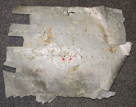
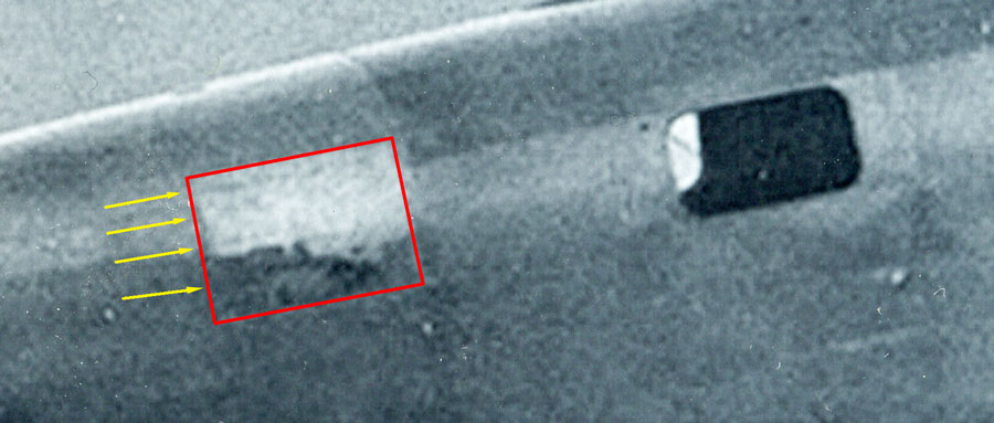
Although working off a low res image and not claiming to be a forensic photograph expert, I consider that image clearly shows the 5/32″ rivet lines of the original surrounding structure, as well as the rivet lines around the entire perimeter of the scab patch.
It DOES NOT evidence ANY intermediate rivet lines? 3/32″? (let alone 4 of them?)
But equally it doesn’t evidence the 3/32″ rivet lines of the stiffeners in the aircraft structure. (which are known to be there)
It DOES NOT evidence ANY externally visible ALCLAD stencilling? (which should be there if the artefact is the patch?)
Of course that doesn’t PROVE they are not there? (just that they are not visible in this image or this resolution?)
But we DO know the Artefact has 4 rows of 3/32″ rivet holes, 1 row of 5/32″ rivet holes and Alcad Stencilling on its Convex (outside).
However!
We can see from the photo “clearly” DOES NOT evidence the lower edge of the patch extending past the double row rivet line of the original lower window skin line?
Yet we DO know the Artefact exhibits a torn tab of aluminium that would extend a full 1 inch below the bottom of the double row rivet line skin lap? in this photo below and certainly 1 full inch lower than the existing lower single row rivet line?
Unless that extending tab of aluminium, and its single row of rivets can be explained, then I consider that tab evidences this is NOT the patch!
Clearly the person holding the artefact against the aircraft at the time the photo is taken, is implying that its lower rivet lines are on that double row rivet line/stringer, but the tab then “destroys” that hypothesis.
If you “lift” the artefact UP so its bottom edge now aligns with the double row of rivet lines that form the original lower window skin line?, then you create a 5th intercostal or stiffener row of rivets?
It seems someone in Tighar realised the same issue!
The original structure, removed to accommodate the window modification, only had 2 stiffeners where Tighar now claim there were 4 or perhaps 5?
They claim the explanation of the extending tab of aluminium is due to an additional stiffener fitted along the edge of the existing double rivet row stringer.
Strangely, they claim the designer of the patch used 5 horizontal stiffeners were only 2 previously existed, but chooses not to fit any vertical stiffeners where 1 previously existed?
However, the rivet holes on the artifact indicate the use of larger rivets (5/32″ rather than 3/32″) than were used on the window frame; and the space between the two lines of rivets in the staggered row implies the addition of another stiffener.
The pitch (distance between rivets) along the bottom edge of the artifact is irregular in stark contrast to the precise pitch of the parallel 3/32″ rivet lines. The metal sheet tore along the bottom line of rivet holes like a piece of paper tearing along a perforation. The rivets didn’t fail, the skin failed. At a point where there is a pronounced gap in the perforation, the tear jumped to the second line of rivets before jumping back to the first line, thus creating a “tab” of metal
.
That “Might” be explained if the patch rivet lines were either side of the existing double row of rivet lines in the existing lower stringer?
but IF that IS THE CASE?, that would suggest that the patch sat over the top of the existing double row of 5/32″ rivets in the existing lower stringer, and these being Dome head rivets rather than counter sunk, would cause the skin to buckle up and then down between the “new” lower stringer, and the final location of attachment to the existing skin?
To hold that skin / patch down, would require the final edge of the patch to be securely riveted along its edge, and some distance lower than that double rivet line stringer?
If the existing 5/32″ double row rivets are left in place, then why is 5/32″ holes used in the lower row of the Artefact as against the 3/32″ used in the remaining 4 rows?
YET, the new photos above , CLEARLY show the patch finishes FLUSH with the bottom of the existing double rivet row stringer.
If THAT is the CASE, the bottom edge of the patch is clearly riveted along that existing stringer, most likely with a double row of 5/32″ rivets in place of the original rivets in those same rivet lines.
But as discussed above, that DOES’NT align with the remanent rivet holes left on the artefact with more than 1″ between the holes in the tab, and the tear line below it.
It seems clear from the photo that the patch is riveted along its lower edge and that aligns with the double row stringer as seen by the skin lines either side of it. That dispels the argument of a stiffener directly above the original stringer, or a double rivet line that sits either side of that original stringer as the patch does not extend lower than the stringer.
Also, if you now “lift” the artefact up by an inch so its lower tab is level with the bottom f the existing skin lap on the double rivet stringer, then the top of the artefact starts to compromise the top boundary of the window frame?, and bring the top 3/32″ rivet line closer to that point as well, rendering it less likely to be required in the first place?
“If” the artefact “is” the patch, then the lower rip on the tab will more than likely equate to the top row of the 5/32″ rivet line of the original double row stringer, assuming they are holding down the bottom edge of the patch?
“But” if that “is” the case,
– then why is the first row of intermediate rivets above it also 5/32″ while the remainder are 3/32″?,
– why is the rivet line un-even at the tab position,
– and what is the remaining height of the window hole to accommodate the artefact being lifted so high by more than 1″,
– and where does that position the upper row of 3/32″ rivet line, let alone the upper torn edge?
Lets go back to the NTSB Report of 1992 for some independent analysis?
http://tighar.org/Projects/Earhart/Archives/Documents/NTSB_Report/ntsbreport.html
2-2-V-1 Sheet
The sheet was a comparatively large piece (23 inch x 19 inch) of 0.032 inch thick aluminum alloy, shown in figure 1, with a pronounced curvature across the short dimension. The sheet had four rows of evenly spaced 3/16 inch diameter rivet holes and one row of 5/32″ holes along its long dimension. Measurements determined that the rivet rows were not parallel but rather showed a slight convergence. Nominal spacing between rows was about 4-1/4 inches at one end of the sheet and 1/8 to 1/4 inch closer at the other end. The skin around these holes was, in general, dimpled inward toward the concave side of the sheet suggesting that the sheet had been area loaded from the concave side while the rivets and underlying structure were intact. The remains of a solid brazier-head rivet were found in the hole denoted by arrow “R” in figure 1. The manufactured head of the rivet was on the convex side of the sheet and was marked with a single round dimple in the center of the head, as shown in the right center photograph of figure 1. The dimple usually signifies a 2117 aluminum alloy rivet. The length of the undeformed rivet shank (distance between the manufactured head and the formed head) indicated that the skin had previously been attached to an approximately 0.06 inch thick underlying member. The faint outline of 1/2″ tall letters “AD” were noted on the convex side of the sheet in the circled area in figure 1A and are shown at 2X in figure lB.
The sheet was bounded by fractures on all four sides. On one side the fracture ran generally along the line of larger 5/32 inch diameter rivet holes. The fracture intersected all of the 5/32 inch diameter holes except for the three denoted by arrows “H” figure 1. The rivet holes in this row were nominally spaced at 1-1/4 inch intervals except for the three unfractured holes which were not evenly spaced. Post separation abrasion and erosion damage had obliterated the fracture faces and positive determination of the modes of fractures could not be established. However, the fracture geometry along the line of rivet holes (upper edge of sheet in figure 1) was consistent with tearing separations in both directions away from the area of the intact holes, as indicated by the unlabelled arrows in the upper photos of figure 1. Also, deformation adjacent to the fracture line located by brackets in figure 1 indicated that the sheet had been folded 90 degrees toward the convex side prior to separation.
Other questions not explained by the Tighar Hypothesis are:
Assuming this artefact IS the patch, and was custom made for that role in Miami:
Q1.Why is the 4 rows of 3/32″ apparently precision drilled in their layout and hole spacing at 1″, as against being a field modification?
Q2. Why do the 4 rows of 3/32″ holes have a slight convergence, and to which direction do they converge?
(if they converge towards to the nose or RHS of the Convex side, this would seem to rule the artefact out for the patch?)
(The converse would not Evidence this is the patch, but would support that theory)
Q3. Why is the 5th row at 5/32″ if they are into a new stringer? and not into the 5/32″ holes of the existing stringer
(as against simply being 3/32″ and 1″ pitch like the other 4 rows)
Q4. Why is the 5th row a different hole pitch ie 1-1/4″?, implying it was precision drilled to be 5/32″ from the outset?
Q5. Why is the 5th row of 5/32″ holes at an different spacing only where the tab is located
(it doesn’t align to the location of the heavy vertical frame at station 307
as in the current Tighar positioning is quite a distance “aft”) (+ 4″?)
I am “open” to being convinced of the Artefact being the patch, but its only “fingerprint/DNA” SO FAR! is its external dimensions appear to be smaller than that of the patch (subject to accommodating the lower tab?) – I don’t accept any of their other claims of evidence support their Earhart forced landing on Gardiner Island hypothesis, hence this piece of aluminium has no head start in its job to convince me than the other 10 pieces reported by the NTSB Report?
I am not convinced yet that there is any correlation between the patch and the artefact in regards to:
1. Rivet hole sizes
2. Rivet line positions
3. Number of stiffeners and hence rivet lines.
4. Skin thickness
5. “Alclad” Stencilling visible on the convex / external face.
6. Date “Alclad” stencilling introduced?
Hence with the un-satisfactory explanation of the lower 5/32″ rivet line on the artefact and its alignment to the lower edge of the patch and its existing 5/32″ double rivet rows, at this time I seriously doubt that it is the patch.
I would be keen to see larger format scans of the patch photo above, as it seems far clearer and more interpretable than the one used on Tighar’s own analysis and its promotion to the media. (and why is this photo not already being used for those two purposes)
I am pleased that Tighar is taking a methodological approach to their study of this piece of airframe skin, it is clearly the only thing they have found that has anything to do with aviation, but like the other 10 items in the NTSB report, could simply be from another aircraft type, US or Japanese, and from a part not quickly identified in the Tighar Commission workshop at the NMUSAF.
Given the date it was found, It “could” in fact be from a post war civil type?
Regards
Mark Pilkington
. [/U]Numerous photographs show that Alclad in the 1930s was stenciled with “ALC” and not “ALCLAD”.
This information has been verified by the Alcoa company, who have stated: “Categorically, this portion of airframe cannot have originated with the Earhart airplane but is from a post-1943 constructed craft”
Thats the Null hypothesis!
Where as the Tighar Hypothesis is:
That is clearly a minor issue compared to the “Many” items of evidence that Earhart and Noonan ended their days on Gardiner Island (male skeleton, womans shoe, face cream bottle, sextant box, turtle bones, and now an evidenced pierce of aluminium used as patch on the Lockheed in Miami)
Given the “extensive” forensic photographic analysis of this item’s “fingerprint/DNA” ( which proves beyond doubt to Gillespie), its therefore clear this sheet of Alclad made and fitted to the Lockheed in Miami in 1937 is carrying remnants of the “Alclad” stencil thereby proving Alcoa is wrong! (Smiles)
So there is no evidence of time travel, just an error in Alcoa’s records! and analysis, clearly Alcoa’s forensic research is not as good as Tighar’s.
For his next trick Gillespie will levitate by pulling very hard on his shoe strings!
The link at the bottom of your last post was quite interesting reading Andy, the “Irene is really Amelia” theory is clearly far fetched and denounced by the woman herself and her son.
But that story does lead the reader back to the wider story of a forced landing in the north on Mili Atoll, capture by the Japanese and relocation / execution on Saipan, with the various eye witnesses who testify to various portions of that outcome?
Elements of it seem more credible than the Tighar hypothesis. Of course it opens up suggestions of espionage, political and military intrigues/coverup and the US being aware of her predicament from the beginning, and intentionally focusing the search elsewhere? (Gardiner Island in the south).
If “anything” of the claims of “official coverup” was true? it would put Hillary’s past support (as Secretary of State) for Tighars efforts in an interesting light?
Like the Rabaul story, it relies on snippits of testimony that if accepted, claims conclusive eye witness evidence of the Lockheed and/or Earhart / Noonan being identified after the disappearance, something which does not exist in the Tighar theories , other that this finger print/DNA sheet of 1937 “Alclad” – hence why its so critical to their fund raising.
I read somewhere yesterday that they had launched the fundraising effort for this next expedition to raise $3M back in April but raised only $4k from those efforts – perhaps explaining the more “confident” claims being made in this current and relaunched fund raising drive?
I still tend towards both being lost in the “crash and sink” scenario after obvious radio errors and possible navigation errors, but a flight north (on the North/South line) and crash at Mili Atoll is as “possible” as going south to Gardiner, its the stories that lead from there that become more questionable?
(Not unlike Bader and a certain hotel?)
Regards
Mark Pilkington
http://www.miamiherald.com/news/local/community/miami-dade/article3483396.html
Using computer enhancement of the photo, snapped moments before Earhart’s plane took off from Miami on her fateful trip, investigators say they have matched a chunk of airplane wreckage found on the Pacific Island of Nikumaroro to a repaired panel on the fuselage of her aircraft.
“As far as we’re concerned, we’ve got a piece of Amelia Earhart’s plane,” said Ric Gillespie, executive director of the International Group for Historic Aircraft Recovery (TIGHAR), which has been searching for the aircraft since 1988
.
So that’s proven it then!
Now we just have to raise that “anomaly” with lots of funding for the next expedition!
Cosford have nearly finished with their lemon juice treatment of the Do-17, better let them know there is a Lockheed 10 about to arrive!
Regards
Mark Pilkington
And this is the second fingerprint/DNA.
There is a double row of staggered rivets on the centreline fuselage longeron that formed the lower edge of the custom window.
They propose that the artefact exhibits tear lines consistent with being double row – staggered riveted.
“YET” a portion of the artefact extends well past the depth of the double row of staggered rivets and only exihibits a single row of holes?
Why? / How? can you argue a tear line along a surviving single row of holes is evidence of there being a double row of staggered rivets, when your item then so conclusively debunks that theory only inches further along that same row?, where clearly there is no second/staggered row of holes?
Regards
Mark Pilkington
You have to admire that TIGHAR lot though: they’re always on the verge of something that never happens or launching an expedition to investigate a smudge on some new piece of photographic ‘proof’, and despite the fact that we know it’s just an elaborate means of having on a nice Pacific holiday every so often, we (I) still make the mistake of reading the latest ‘developments’, even though there aren’t any!!!
And despite despite having absolutely no evidence (or likelihood thereof), they’ve managed to keep this story in the headlines and many people who should know better (including me!) still waste their time commenting on it!!
This is the source of their smoking gun.
“Someone” has forensically identified 4 parallel rows of rivet lines on this blurry photo of the window patch on EH’s Lockheed.
“Then” it is discovered that the Tighar Artefact has the near identical 4 parallel rows of rivet lines on it!
“What” a co-incidence, the fingerprint/DNA matches!
Or more a fact of trying to see what you want to see?
Of course I wonder how many other people with an understanding of 1930’s aircraft construction methods, good eyesight and ability to scrutinise blurry photos (but who had never seen Artifact 2-2-V-1) could find those same 4 rivet lines in the photo that Tighar can?
A house of cards requires the base to built solid, otherwise it will fall down.
Regards
Mark Pilkington


 Sign In