No, the sphere of this and that is marketing PR,
but the benchmark is area square, lest L.M even managed to re-write this’un :rolleyes:
Actually that is incorrect. RCS units in both the m^2 and dBsm are a measure of radar return off a subject relative to a metallic sphere.
RCS in m^2 is the cross sectional area of a metallic sphere that would return the same scattered signal strength as a particular target in the optical scattering regime.
RCS in dBsm is the signal strength off a target relative to a metallic sphere with a cross sectional area of 1m^2
They use a sphere as the benchmark because it has a uniform RCS from all angles and frequencies when the sphere is large relative to wavelength.
F-303 is completely undetectable by any means (EO, radar, IR) due to such awesome stealth features as not being able to fly. :eagerness:
LIES!!!! It is already operational and is ready to crush the American devils …. see!!!
1.44 looks great, too.
Why is the 1.44 included in this? It’s not a stealth fighter. Besides….
[ATTACH=CONFIG]219277[/ATTACH]
… gentlemen, this competition is OVER!!!
You will also need a maws so you’re adding extra weight. Unless you have decent sized and powered apertures around the aircraft you won’t be detecting modern 5th gen threats or missiles until its too late.
The responses above gloss over some of it. Basically the benefit of aperture size comes down to 2 reasons, Range and Resolution.
The single pulse max range equation is as follows:
[ATTACH=CONFIG]218576[/ATTACH]
With just some of the variables, derivatives of the equation can be used for estimating differences in detection range performance between apertures and for predicting the difference in range at different power outputs and with varying target RCS.
Examples.
You can predict that a radar with a Ps of 20kw is going to have roughly an 19% range advantage over a radar with a Ps of 10kw. (20/10)^(1/4).
A legacy fighter with 3m^2 RCS will be detected at 7.4 times greater distance than a stealth fighter with RCS of 0.001m^2. (3/.001)^(1/4).
The part of the equation that is dependant on aperture size is gain (G), or the ability of the aperture to focus most of its energy into a tighter beam and receive more energy on return.
G = 4*pi*effective area/wavelength^2
Effective area is based on physical area and aperture efficiency. As you can see with the relationship of the variables, as area increases, so too does gain and subsequently range. You can also see that gain increases with shorter wavelength too, but not necessarily range because as mentioned above, the higher the frequency, the more EM waves are attenuated within the atmosphere. Also, wavelength is a numerator of the greater Rmax equation from earlier.
[ATTACH=CONFIG]218574[/ATTACH]
Beamwidth which dictates resolution is based on wavelength/antenna width or height for azimuth and elevation respectively. So the wider a radar, the more accurately it will calculate the heading to the target. This is why low band radars tend to be huge and cumbersome while engagement radars can be smaller but still benefit from being larger. From what I’ve read the king of mobile engagement radars is the AN/TPY-2 (or soon, an adaption of it called GBX where two TPY-2’s are stacked on each other) due to its large size, power output and aperture efficiency.
So based on the wavelength/width rule, you can’t just exploit the radar equation and the issue of atmospheric absorption by placing a l-band radar on an aircraft. Due to the inherently small antenna size on aircraft, the accuracy of the aperture would be horrible and unsuitable for getting a weapon close enough to the target so its within the weapon’s own radar FOR.
Quick calc using some Lift and Drag coefficient graphs I found in an article from the world academy of science, engineering and technology. The object was wind tunnel tested from various AoA’s and they also used 2 separate prediction techniques to develop the graphs. I made an assumption the graphs would be linear and expanded them up to 26 degrees AoA.
Object was a cone nosed cylinder (the context of much of the document is missiles). Haven’t triple checked the formulas yet, but its coming along. When I get back from hols will tweak it with built in tables so I don’t have to refer to the ones on the right and will add the ability to predict G’s needed to intercept throughout the flight while the target is manoeuvring using augmented proportional navigation formulas to predict missile turns.
Model only considers body lift and cross sectional area only, no wing lift. Will add that later. If everything’s working ok and even remotely accurate, then 40G capability is most certainly a structural limit at low altitude, but a lot depends on control surface deflection angle and maximum AoA.

tried to calculate proportionally based on a single “assumed” quantity
I had thought to calculate using a similar method, unfortunately there’s a key piece of information missing.
Your data is: 40G
Your assumption is: low altitude
The rest is simple proportional calculation based on air density, velocity and a proportional Cl chart from Wikipedia. You might notice the support text with the chart is a protest from someone who thought that calculation of Cl at different speeds and angles DID NOT require wind tunnel testing …. IE. shape is irrelevant (I bet that every modern aircraft manufacturer is forehead slapping themselves at that revelation)
One glaringly obvious area where his whole argument falls over is with a sphere. Is a sphere going to more manoeuvrable at high speed? How about at a higher angle of attack? You might want to check the source he cited for his information because as with your calculations above, I believe he is missing parts of the picture which destroy his results (GIGO). This is why its important to read the REAL sources when citing Wikipedia, rather than from people who frequently omit certain details.
A really important area where your proportional method falls apart is that the G capability for a missile is pretty much always a structural limit and not a possible, aerodynamic G capability. The control autopilots will prevent the missile from exceeding the structural limit. So the missile is most likely able to pull 40G’s all the way up to a certain altitude using a single control plane, then for a higher altitude range is still able to do 40G’s with dual plane control.
So effectively, this means reference area will be very different in the calculations for different altitudes, as the missile’s autopilots will not allow it to hit maximum aoa at low altitude to reach maximum “theoretical” turn acceleration. Accurate Cl’s also become important as well.
Unless you know specifically what is the maximum altitude at which the missile can pull 40G’s, then the proportional method you’re trying to use will fail and most likely by a huge margin.
Only other option (outside of hacking into Raytheon’s servers) is to build yourself a supersonic wind tunnel and calculate Cl yourself and then you can work out a very rough estimate from scratch.
Unfortunately if you sensitivity test even some of the least significant variables, results can vary too much (due to the huge impact of velocity). Small fractional errors in minor variables result in huge changes in performance. You’ll never sort it out with simple, high school maths I’m afraid.
Hi!
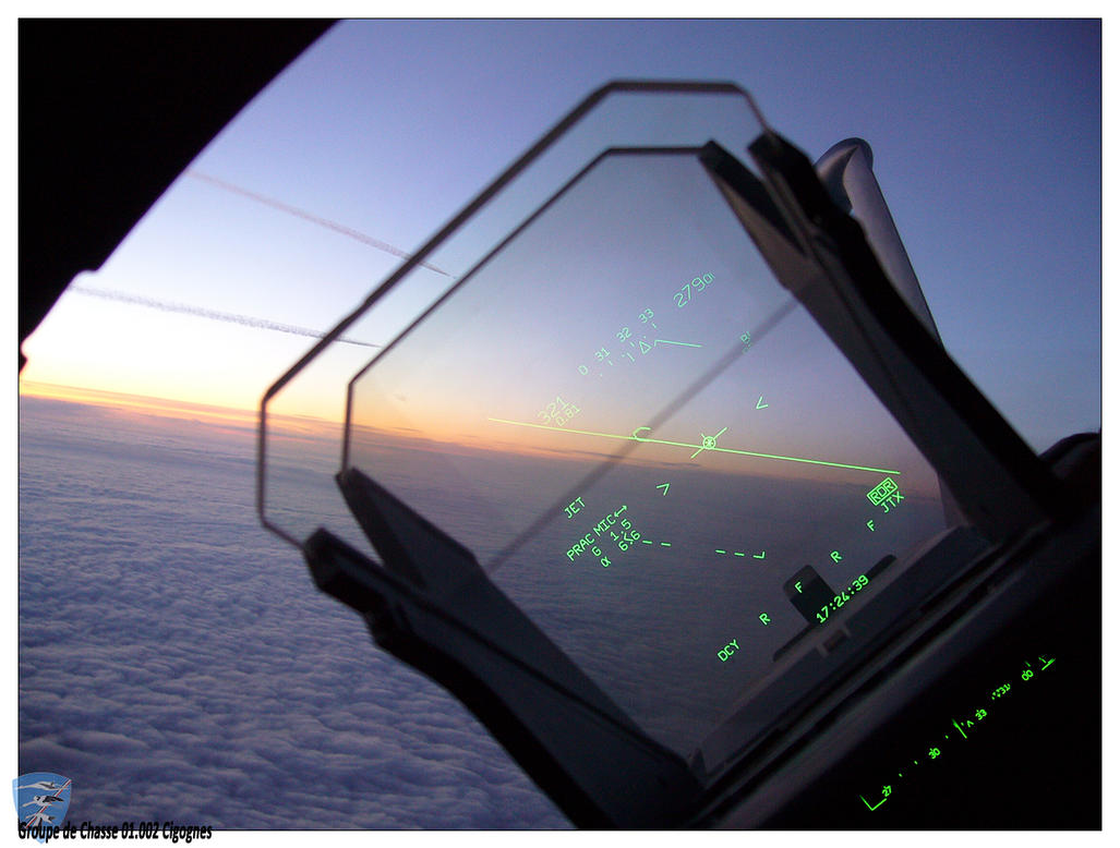
A video of Spanish Typhoon. Poor quality but it’s very exciting. A 1 vs.1 dogfight training with cockpit views:
http://www.youtube.com/watch?v=pQVXa2rK8xU&feature=youtube_gdata_playerBye!
Nice video, its performance looks really impressive. I can see why there was reports it absolutely trounced the Su-30MKI’s and gave the F-22 a run for its money, its so nimble.
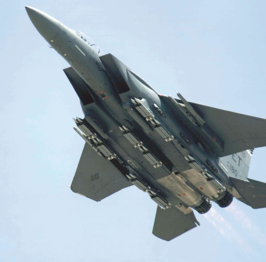
Including the 8 on the wings, plus at least 1 on each of the CFT hardpoints (6), gives a grand total of 34?
Wonder if being dropped from an angle causes any issues with the SDB’s wing deployment and roll manoeuvre.
F-15E downing a hornet 😉
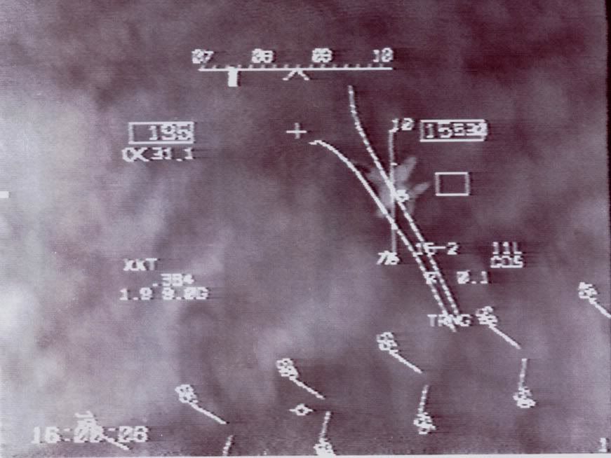
Not a HUD kill, but just a very nice HUD pic.
The navy has ordered 4800 laser attachments so far with 2/3 of ghat order to be completed by early next year. Given that the kits offer a lot more utility to the standard jdam (hitting fast moving vehicles) expect them to become a standard for now.
Specifiacally, which current JDAM model has laser seeker integrated?
GBU-54, GPS/INS + Laser

[QUOTE=Andraxxus;2037180]”Did you? Then can you explain why there are no CFT LH/RH pylons on the 610 gal tank pages you posted, but they are present on the Mk-84 graphs?”
Oops, I took the wrong screenshot the first time, went back and took the right one, then posted the wrong one. No matter, the limits are exactly the same for both.
When limits are concerned, F-16 is A LOT different than F-15; for example, F-16 does not have any G limits depending on payload
I would doubt that until I saw the data. If an F-16 was pulling 9G’s at high speeds, an MK-84 would be putting at least 18,000lbs of force on the few fasteners securing its pylon + aerodynamic forces in numerous directions. Unless I saw it on the 1-2 document, I’d never believe it.
you are correct; however see my other posts with basic question: Is LANTIRN always necessary?
Well if you want to use the laser seekers on your JDAMs for better accuracy, you need a pod.
Good research Shiny. I admit I googled it earlier but couln’t find anything. At least its been settled once and for all
Cheers, I googled for a while too as I knew the statement was wrong and why and was interested in confirming it. Didn’t realise it was just sitting in the F-15 manual I found a few weeks ago. I expected it to be a separate doc like with the F-16.
Holy cow this has got to be the winner, its real and has room for 8 more on the wings. 20 SDB I’s.


 Sign In