i don’t know how accurate these graphs is but anyway :
AIM-120B
R-27ER
R-27R
RVV-AE vs AIM-120A
AIM-9X ,R-73
I’ve never heard of such use, but its possible for some SAMs like SA-N-6 to target ground/sea targets. Illumination radar is just pointed towards the target on the ground and SARH/TVM missile homes in, without knowing the specifics of the target.
Theoratically, IF there is a way for pilot to override the automated tracking algorithms, and IF he can manually steer the CW illuminator, he can direct a CW beam to any target he wants(via hat etc) and use SARH missile for A-G roles. It would be very similar to manual laser-guidance, but with a radio signal implementation. Newer missiles like AIM-120 are smarter and A-G roles are impossible changing the software on the missile.
i do heard that all SARH SAM on ship have secondary anti surface function too, but iam not sure if AIM-7, R-27 could ever been used like that
In my dim and distant past, I was an air radar tech in the RAF. Now my knowledge of modern radars is zilch but I’m guessing that there would be too much background clutter for the radar to find, let alone, lock on to a moving target. It also depends on what type of seeking head the missile has.
i do understand that ground clutter is a big problem but wasn’t modern radar can distinguished between an aircraft and chaff by replying on doppler effect? would that not work again ground target? , btw how about modern radar that have GTMI, or SAR mode?
i strongly suspect its a child
iam probably older than you, but that not the point, no matter what age you are if you stop having questions then you would stop learning new things! , i would rather be a curious child and learn new things everyday, boarding my knowledge than an arrogant old fart who stop asking questions caused he think he knows it all
I believe its mostly a software limitation.
certainly if the aircraft’s computer can be programmed with an additional mode to use air to air missiles whilst the radar is in ISAR / ground mapping mode. there’s practically no reason why you couldn’t do that. But I am guessing most countries don’t want to even think of wasting precious air to air missiles on targets for which more suitable weapons are available… and thus customers are unlikely to pay a few million dollars to reprogram their computers in order to be able to launch air to air missiles against surface targets.
i know air to air missiles are too expensive to use to attack ground targets but since i recently read about Raytheon advertising their AIM-9x can be used to attack small boat, i was wondering if older radar guider missiles could do similar thing( less effective obviously but still)
btw i think advantage of AAM is that they are quite fast and can be carried in great number
The proximity fuze will detonate the warhead as the missile nears the ground, possibly making it ineffective against a ground target.
what if the missiles was in top attack mode?
Yeah, he wants to suspend reality by ignoring the subtleties of facts
This kind of question is really nonsensical when you consider the OP is a thinly veiled attempt to manufacture a controlled response.
not really, i was just curious, not everyone know everything, sometime limited knowledge in some areas can lead to wrong conclusion that why i ask questions to find out where i may be wrong.. etc and i think it good to ask questions too, admitted limited in knowledge and learn is much better than pretending to know everything and stay ignorance
Sorry – not even Sukhoi is claiming that the extended tail houses a MAD detector, just defensive electronics.
The torpedo is part of its anti-surface naval warfare task.
i think it does
The Su-32 multi-role aircraft can fly maritime patrol, anti-ship attack, day/night all-weather precision strike against small-size and moving targets, low level attack, and anti-submarine warfare missions engaging enemy aviation using short and medium range air-to-air missile
http://www.deagel.com/Long-Range-Attack-Aircraft/Su-34_a000181001.aspx
The Su-32FN is a unique maritime patrol, Anti-Submarine Warfare and maritime strike derivative of the T-10V design, designed to perform littoral and coastal maritime roles. The inclusion of an ASW capability in this aircraft created much debate during the 1990s, as this role in the West has traditionally fallen on specialised airliner derived airframes. The Soviet LRMP fleet comprised variants of the Tu-142M Bear F and Il-38 May, derived from the Il-18 Coot airliner.
To understand the reasoning behind an ASW equipped strike fighter it is necessary to explore latter Cold War Soviet maritime doctrine, and the concurrent US Navy maritime strategy. During this period the Soviets envisaged their ballistic missile armed SSBN fleet operating in bastions near to Murmansk/Polyarnyy and Vladivostok, and other fleet elements defending the Baltic and Black Sea ports. In the event of a full scale war with the West, the bastions, Baltic and Black Sea would be the hunting ground for US Navy and Royal Navy SSNs, while the airspace would be actively contested by F-14s from US CVBGs and land based US Air Force F-15 sweeps. This is an environment which is not conducive to the longevity of LRMP turboprops like the Bear and May. This presented the Soviets with genuine issues in performing maritime patrol and ASW tasks and a highly survivable airframe was a must. As the bastions and approaches to Baltic and Black Sea ports were close to existing land bases, a large strike fighter could provide credible on station endurance, where the station was perhaps 30 minutes of flying time from a runway. While a four hour on station endurance may be modest compared to a turboprop LRMP airframe, proximity to relief aircraft waiting to launch still makes this a viable concept.
The result of these pressures was the Su-32FN, devised for the AV-MF to absorb the roles of the AV-MF Su-24 Fencer regiments, and include the ‘new’ ASW role. It is essentially a supersonic, highly survivable land based equivalent to the Lockheed S-3 Viking.
The principal deviation from the baseline Su-32MF/34 was to be the addition of the ‘Morskaya Zmyeya’ (Sea Snake) maritime patrol avionic suite, since then to be fitted in the reported to be collapsed Indian Navy Bear F avionic upgrade, and a suite of maritime strike and ASW weapons. The suite is claimed to include an Electronic Support Measures receiver and Magnetic Anomaly Detector.
For ‘classical’ maritime strike roles, the Su-32FN is to be armed with up to six Kh-31A or Kh-31R ASMs, six Kh-35U ASMs, up to three Kh-59M/D stand-off missiles, the potent supersonic Kh-41 Moskit (Sunburn) and 3M-54 Alfa supersonic ASMs.
Photographs indicate that the centreline adaptor for the Kh-41, developed for the Su-33, would be reused, although one mid 1990s report claimed carriage of two rounds on wing stations. Original Alfa missile mockups were also photographed on the inboard wing stations, this missile has since evolved into the 3M-54/3M-14E (SS-N-27) Club series.
The more interesting stores are lightweight ASW torpedoes, carried in pairs on stations 8 and 9, for a total of 4 rounds, and a conformal centreline pod which can be loaded with up to 72 sonobuoys of various types. An ASW patrol weapons mix would probably involve a mix of these stores, drop tanks and depth charges.
.
The principal deviation from the baseline Su-32MF/34 was to be the addition of the ‘Morskaya Zmyeya’ (Sea Snake) maritime patrol avionic suite, since then to be fitted in the reported to be collapsed Indian Navy Bear F avionic upgrade, and a suite of maritime strike and ASW weapons. The suite is claimed to include an Electronic Support Measures receiver and Magnetic Anomaly Detector.
French talking. What about Atlantique2?
MAD is excellent to refine torpedo solution btw.
first time i heard of that aircraft
Anti-Submarine Warfare Helicopters
An ASW helicopter will traditionally team with a surface ship to prosecute an underwater target. The helicopter will deploy multiple sonobuoys and then utilize tactical sensor systems installed on both the surface ship and the helicopter in order to localize the target. The helicopter’s crew can track and, if necessary, attack a submarine with torpedoes.
The ASW mission requires a helicopter crew to track submarines using sonobuoys. Sonobuoys are passive or active sonars that can localize a sound source. Sonobuoys are placed in patterns and provide the direction from which a sound is emanating underwater.Typical sonobuoys used by the Navy include Low Frequency and Ranging (LOFAR) and Directional Frequency and Ranging (DIFAR). Bathythermograph sonobuoys create a profile of water temperature versus depth. ASW aircraft are predominantly equipped with sonobuoy launcher systems which utilize cartridge-activated devices, such as pyrotechnic squibs or high-pressure gas bottles, as the energy source for ejecting the sonobuoys. Gas is discharged at high pressure for high reactive loads at low volume entailing very sophisticated breech and firing mechanisms within separate metal, plastic or filament-wound fiberglass sonobuoy launch containers.
Dipping sonar allows the helicopter to listen for and transmit underwater electronic signals while in a “hover” or stationary mode. The aircraft typically hovers at an altitude of 50 to 300 feet above sea level and lowers the transducer into the water using a powered reel system similar to a fishing reel. The transducer can be lowered to depths ranging from the water’s surface to 2,500 ft. Once lowered to the selected depth, the transducer is activated, generating sound signals and receiving echoes from submerged objects. These echoes can then be processed to identify and locate potential underwater threats.
During the early part of World War II, the Navy Department initially visualized the helicopter as an aid in combating German submarines which were seriously menacing United States and Allied shipping. Original plans called for the helicopters, piloted by Coast Guard flyers, to accompany ocean convoys and operate as scout aircraft from platforms constructed on the merchant ships. The Navy accepted delivery of its first helicopter, the R-4 (HNX-1), on 16 October 1943 and assigned it to the United States Coast Guard, Coast Guard Air Station, Floyd Bennett Field, Brooklyn, New York.Testing of the helicopter’s suitability as an antisubmarine weapon began the following month.
The helicopter could carry a MK IX 200-pound, fast-sinking-type depth charge and drop it after surface contact had been made. The helicopters could be based on destroyers and could be directed by radio to the subs. Then, by hovering until a sonar signature was obtained, they could drop a depth charge and be rearmed by the destroyer. The one thing that had not been considered was that if the helicopter was rushed into mass production, it would inevitably interfere to some degree with airplane production. Thus, the actual value of the helicopter had to be weighed before a production program could be approved. Production scheduling, however, was already a potential problem.
Despite the mounting threat to shipping, the development of helicopters slowed for a year, due to differences between the Army and Navy. The Army felt that it was not its function to develop the helicopter for anti-submarine warfare. The Navy, on the other hand, felt that the Army had been given the job of developing the helicopter and that until this was done, the Navy should not butt in. The Navy based its limited interest in rotary-wing aircraft on the thesis that a helicopter could never be built large enough to carry a sufficient load to be of any value.
To expedite the evaluation of the helicopter in antisubmarine operations, In May 1943 the Commander in Chief, U.S. Fleet directed that a “joint board” be formed with representatives of the Commander in Chief, U.S. Fleet; the Bureau of Aeronautics; the Coast Guard; the British Admiralty and the Royal Air Forces. The resulting Combined Board for the Evaluation of the Ship-Based Helicopter in Anti-Submarine Warfare was later expanded to include representatives of the Army Air Forces, the War Shipping Administration and the National Advisory Committee for Aeronautics. Navy representatives witnessed landing trials of the XR-4 helicopter aboard the merchant tanker Bunker Hill in a demonstration sponsored by the Maritime Commission and conducted in Long Island Sound. The pilot, Colonel R. F. Gregory, AAF, made about 15 flights, and in some of these flights he landed on the water before returning to the platform on the deck of the ship.
In an attempt to make helicopters more proficient in the role of a submarine hunter, a project began in April 1944 to equip them with a “dipping sonar” similar to what blimps carried. The major concern was the noise transmitted to the water by the wash from the helicopter’s rotors. Working off the Cobb, it was found that the noise level was insignificant and did not interfere with equipment operation. During flight operations, it was discovered that the HNS-1 helicopter was extremely helpful when used as a target for the alignment of fire-control radar, anti-aircraft radar and loran testing. This use was so helpful, in fact, that it later became the chief operational function during the war.
Had the submarine menace increased rather than declined in 1942, more resources might have been poured by the United States into the development of the helicopter as an anti-submarine-warfare weapon. The allies eventually solved the problem of the air-gap in the Atlantic Ocean with long-range bombers and escort carriers. Planes from the escort carriers in particular played the role that had originally been envisioned for the helicopter. Rotary-winged aircraft appeared on the scene about two years before the helicopter could be adapted for any type of active anti-submarine warfare role.
As it was, helicopters remained largely untested and undeveloped and thus never played the role that many envisioned for them during the war. Given the declining submarine threat, those that wanted to develop the helicopter found it difficult to shift national policy. Perhaps more important was the fact that technology is evolutionary rather than revolutionary. The helicopter could not be developed fast enough to be effectively used and, so it sat out the war.
In 1946 the Anti-Submarine Helicopter Dipping Sonar program was run by the Naval Research Laboratory in Washington, DC. Helicopters were used during the successful testing of a special “dipping” sonar, a device that is still in use today by Navy ASW helicopter squadrons.
Beginning in the 1950s, the carrier-based air ASW community was one of the driving forces behind helicopter development, and within the HUK groups, HS squadrons deploying active, dipping sonars became a key new addition to the combined arms ASW team. HS squadrons gave the HUK group an active sonar platform with the speed and mobility of an aircraft. The original attraction of an airborne dipping sonar was in cooperative operations with radar-equipped aircraft in operations against snorkelers. The latter would often detect a snorkel, but the submarine would submerge and be lost when it went on battery because no destroyers were within range to hold the contact with active sonar. The ASW helicopter with a dipping sonar filled this gap by holding the contact until destroyers with the endurance to hold the submarine down until its batteries were exhausted arrived.
As ASW against nuclear submarines became more important, HS squadrons also were useful because they could operate in noisy environments where passive acoustics were much less effective, but where screening forces were still necessary, as in the inner screen of a carrier battle group or within a convoy.
Lightweight torpedoes became the weapon of choice for the air ASW community, while heavyweight torpedoes were developed for submarines. Surface ships initially carried both, but came to rely mostly on “thrown” (ASROC) or air-delivered (DASH, LAMPS) lightweight torpedoes.
The culmination of this first phase of the helicopter’s use as an ASW platform was the SH-3 Sea King. The Sea King was too big to be deployed on all but the largest surface combatants of its time, which limited the ASW helicopter to being a carrier-based platform. Smaller ships, such as destroyers, deployed with the the Drone Anti-Submarine Helicopter (DASH) system.
This would change in the early 1970s with the development of LAMPS (Light Airborne Multipurpose System) ASW helicopters. The Light Airborne Multipurpose System combines the SH-60B helicopter with a computer-integrated shipboard system to extend the range and overall capabilities of surface combatants for antisubmarine and antisurface warfare, surface surveillance, and over-the-horizon targeting missions. To enhance littoral warfighting capabilities, the Flight IIA design of the DDG-51 included the capability to support SH-60Bs.
By the late 1990s the F version of the SH-60 was replacing the obsolete carrier-based SH-3H as naval battle groups’ inner-zone ASW helicopter system. The SH-60F employed a new, longer-range active dipping sonar to localize and track submarines, particularly in littoral areas. Future plans call for the conversion and reconfiguration of both the SH-60 B and F classes into a common SH-60R model. The SH-60R program includes a service life extension as well as avionics upgrades, such as the addition of an advanced low-frequency sonar and multimode radar. The aircraft also will be outfitted with gun and missile systems, to enhance performance in littoral regions.
Modern ASW Helicopter’s
Agusta Westland EH101 Merlin
Merlin HM MK1 (formerly Merlin EH101) is an Anti-Submarine (ASW) variant of the EH101 helicopter. It entered service in December 1998, replacing the ageing ASW Sea King (Mk6). The collaborative program began in 1979 through EH Industries – the company formed by Agusta of Italy and GKN Westland in the UK. Designed in Western Europe, it is the largest collaborative helicopter project in history and the most powerful helicopter in terms of military capability. The mission system is world-leading and the weapons system is a significant force multiplier compared with existing capability.
Sonar
Thomson Marconi Sonar AQS-903 acoustic processor
Active/passive sonobuoys
Thomson Sintra FLASH dipping sonar array
NH-90 NFH
The NH.90 is a medium sized, twin-engine, multi-role military helicopter originally envisioned in 1985 but suffering from both technical and funding problems for more than a decade. The programme was only relaunched in July 2000 when a major order was made by the partner countries. Developed in two main variants: the Tactical Transport Helicopter (TTH) and the NATO Frigate Helicopter (NFH) It has been ordered since then by other 9 nations with deliveries beginning in 2006. NH.90 are manufactured in Cascina Costa (Italy), Marignane (France) and Donauwörth (Germany) whilst local aircraft are also assembled in Patria (Finland) and Brisbane (Australia).
As of January 2013, 529 NH90s have been ordered by 14 nations with 133 already delivered. Together they have logged more than 31,000 flight hours.
Sikorsky MH-60MR
The multimission Sikorsky MH-60S Knighthawk helicopter entered service in February 2002. The US Navy is expected to acquire a total of 237 of the MH-60S helicopters, to carry out missions such as vertical replenishment, combat search and rescue, special warfare support and airborne mine countermeasures.
The helicopter began full-rate production in August 2002. As of January 2011 52 MH-60R and 154 MH-60S helicopters were in the service with the US Navy. First deployment of the new helicopter took place on board USS Essex, Wasp Class amphibious assault ship, in January 2003 and a number of MH-60S helicopters were deployed in support of Operation Iraqi Freedom.
The helicopter was originally designated CH-60S, as a replacement for the US Navy’s Boeing CH-46D Sea Knight heavy-lift helicopters in the vertical replenishment role. The helicopter was redesignated MH-60S as a result of an expansion in mission requirements to include a range of additional combat support capabilities. Retirement of the US Navy Sea Knights concluded in September 2004.
The MH-60R is designed to combine the features of the SH-60B and SH-60F.[14] Its sensors include the ASE package, MTS-FLIR, the AN/APS-147 multi-mode radar/IFF interrogator,[15] an advanced airborne fleet data link, and a more advanced airborne active sonar. It does not carry the MAD suite. Pilot instrumentation will be based on the MH-60S’s glass cockpit, using several digital monitors instead of the complex array of dials and gauges in Bravo and Foxtrot aircraft. Offensive capabilities are improved by the addition of new Mk-54 air-launched torpedoes and Hellfire missiles. All Helicopter Anti-Submarine (HS) and Helicopter Anti-Submarine Light (HSL) squadrons that receive the Romeo will be redesignated Helicopter Maritime Strike (HSM) squadrons.[16]
During a mid-life technology insertion project, the navy will upgrade the radar capability of the MH-60R fleet to the AN/APS-153 Multi-Mode Radar with Automatic Radar Periscope Detection and Discrimination (ARPDD) capability.
SH-60F CV Helo variant
The SH-60F CV Helo variant of the Seahawk is equipped to carry out the anti-submarine warfare role in the noisy inner zone of a carrier battle group. It is equipped with the AQS-13F active dipping sonar system, supplied by L-3 Communications – Ocean Systems, an ASN-150 cockpit management and tactical data processing system.
Super Lynx 300
The Super Lynx 300 ASW/ASuW is the latest generation of the would leading multi role, multi mission maritime and utility aircraft from Agusta Westland. The aircraft is an evolution of the highly successful Lynx helicopter that, for more than 40 years has successfully met the demanding operational needs of 15 nations in both the maritime and land environments. This purpose built military aircraft with fully marinised airframe is designed with small ship operations in mind and benefits from a low centre of gravity, Blade and Tail fold together with excellent cross and tail wind operating envelopes. The superb twin LHTEC CTS800 engines provide excellent hot and high performance and single engine capability, these ruggedized characteristics, optimisation for the harsh maritime environmental and ship-borne operations make it the number one choice when operating from small ships where Flight Deck and Hangar space are at a premium. With its fully Night Vision Goggle (NVG) compatible cockpit, integrated avionics suite, and wide selection of optional equipment, the aircraft delivers a day/night, all weather capability for Tactical (Anti Sub-Marine, Anti Surface), Search And Rescue (SAR) or Utility support missions.
Z-9C Anti-submarine warfare (ASW) Helicopter
Chinese Z-9C Anti-submarine warfare (ASW) of the People’s Liberation Army Navy Air Force (PLAAF) which is equipped with a pulse-compression radar and low frequency dipping sonar to aid in Anti-submarine warfare (ASW).
ASW variant produced for the Pakistan Naval Air Arm. Configured with pulse-compression radar, low frequency dipping sonar, radar warning receiver and doppler navigation system, it is also armed with torpedoes for use aboardPakistan Navy’s F-22P Zulfiquar class frigates.
At present, Z-9C anti-submarine helicopters and British and French naval equipment use a lot of “Lynx” anti-submarine helicopters in the vast majority of performance at the same level, its maximum is not small enough to carry sonar buoys, so that it served as antisubmarine defense mission there a great lack of. As an internal equipped with sonar and amplifiers, antennas and anti-submarine helicopter with a contact acoustic detection equipment, sonar buoys may be in the submarine-infested waters by a certain law into the sea, by setting a good program down to a predetermined depth, in order to actively or passively work, according to the submarine speed, quietness, and sonar buoy the hydrological conditions of work, its detection range of submarines can reach 1.5 to 3 km, and anti-submarine helicopters, communication distance of 15 to 20 km. Passive sonar buoys used for a wide range of sea submarine target detection, you can put 3 to 5 pairs of 300 square kilometers of the vast waters effective detection, but can not accurately determine the distance and direction the submarine, it is generally needed and active sonar buoys (or dipping sonar) used in conjunction in order to determine elements of the submarine campaign, Xie calculate the submarine campaign data, determine the program and select the anti-submarine weapons attack attack.
2. Knife Fight in a Phone Booth: Submarine versus Submarine
The baffles are the area around a vessel in which its sonar is ineffective, forming a blind spot or dead zone. For most ships and submarines, this involves a cone about 15 degrees wide extending aft from the stern, in water disrupted by the screws and the vessel’s own passage
Image credit: Dan Short (DanMS).
An effective tactic for submarines, especially, is to close on a target, in the area of its baffles, and then shoot a torpedo from close range. There is virtually no opportunity for counter-attack or escape. Nuclear submarines, with their near limitless endurance and high speed capability, are especially good at exploiting this tactic. Even when you have no intention of attacking, placing your vessel in the baffles of the enemy can permit you to track him, trail him, and remain undetected.
There are a few tactics which can help defeat this approach. Turning your ship, or submarine, suddenly through 90 to 360 degree turns (the famous “Crazy Ivan”) will place your sensors so as to listen down your former baffles.
In the following image, a Soviet Project 671RTM (NATO Victor III) class nuclear attack submarine has turned to port to check his baffles. The trailer, a US Navy Sturgeon (SSN-637) class boat, having detected the “Crazy Ivan” maneuver, has stopped his screw and gone quiet in an effort to maintain the subterfuge. If he is successful, the Victor III will make a complete 360 degree turn, around the Sturgeon, and then return to his original course, having never detected the drifting American sub. (Also visible is the Sturgeon’s streamed towed array).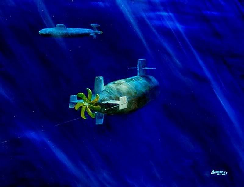
Image credit: Jim Christley, “Trailing”, subart.net
On the down side, any abrupt course change will also produce a pocket of disturbed water, called a “knuckle” that will act as a blind spot for both active and passive sonar systems. Scott Gainer says it still beats a torpedo enema anyday, though, and its difficult to disagree. 😆
If more than one ship is traveling together, they can periodically turn and search each others’ baffles using a crossing maneuver. And, when on the attack, one ship can stand off and conduct a search while the other deploys ASW weaponry, in order to avoid the submarine slipping under and escaping through the attacker’s baffles, or during “blue outs” caused by weapon detonations (a “blue out” is a disruption of the sound path caused by the loud and sudden release of acoustic energy and bubbles in an underwater explosion).
Sonobuoys, dropped from the air or from ships, and helicopter dipping sonar employed to the rear of a formation, in the area of its baffles, can together provide a good plan to counter any approach from the rear.
3. Most Feared: the ASW Aircraft
The aircraft – whether fixed wing or rotary wing (helicopter) – is without a doubt one of the best tools in the ASW arsenal, perhaps the penultimate “force multiplier” from an ASW perspective. While the traditional ASW hunters – surface ships and submarines – have an equal (or better) chance of becoming the “hunted”, the aircraft is perhaps the only weapon against which the submarine has little recourse (though even this is changing, more on that later).
Even for aircraft, however, the task of searching a vast ocean for a small, likely submerged, target is a hugely daunting task. And, as I’ve mentioned before, it can be pretty boring until you actually find something.
The principal advantage of an aircraft in the ASW role is speed, as compared to other platforms: speed in getting to the patrol area, speed in searching that area, and speed in prosecuting a contact.
Helicopters
Commensurate with the expanding size of the Soviet submarine fleet in the 1950s came a realization within the US Navy that its own increasing sonar detection ranges were outstripping its ASW engagement range. In particular, the RUR-5 ASROC (Anti-Submarine Rocket) then under development would not have the range to take advantage of the capability of the SQS-26 hull sonar.
A solution was found in the QH-50 DASH (Drone Anti-Submarine Helicopter), a small coaxial rotor equipped and unmanned helicopter which could operate from ships too small to have extensive aviation facilities, and moreover, operate in bad weather, even up to Sea State 6. (Something helo pilots did not (and do not) look forward to). Spooling up and taking off within two minutes of engine start, the DASH could deliver two Mk 44 lightweight homing torpedoes or a single Mk 17 nuclear depth charge to a sonar contact up to 22 miles away.
A QH-50A DASH operating off the Fletcher class destroyer USS Hazelwood (DD-531)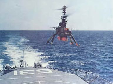
Image credit: Gyrodyne Helicopters.
To illustrate the urgency of the Navy’s desire for ASW stand-off weapons, production of the DASH was authorised a full year before the first model had ever taken to the air. By late 1963, funding had been approved for production of three QH-50C aircraft for each of the Navy’s 240 FRAM I and II destroyers.
High attrition rates and the intervention of a non-ASW war in Southeast Asia (Vietnam, of course) led to the premature demise of the program in 1970, but the versatility of the shipboard ASW aircraft had clearly been established.
Ship based helicopters continue to be one of the most useful and flexible of ASW platforms, especially in terms of their multi-mission nature and ability to move out ahead of their host ship, thereby extending the range of the defensive zone. A modern naval helicopter can be packed with ASW relevant sensors – sonobuoys, a dipping sonar, radar, FLIR, ESM, etc – and can carry enough weaponry for one or two engagements, typically a pair of lightweight torpedoes.
The dipping sonar is the ASW helicopter’s forte – the ability to hover right above a suspected enemy submarine, hammer it with active sonar, and thereby precisely determine its position as a prelude to a weapon drop. As we’ve learned throughout this Tactics 101 discussion, a submarine whose stealth has been compromised can quickly find itself in a world of hurt.
Active dipping sonar deployed from helicopters are the answer to the threat from quieter submarines in coastal areas by employing much lower frequencies, coupled with new transducer and beamforming technology.
Cold War ASW Icon: the P-3 Orion
The Lockheed P-3 Orion is perhaps the iconic symbol of airborne ASW during the Cold War era, certainly setting the standard for NATO maritime patrol and reconnaissance. A testament to the importance placed on the Orion’s role by the US Navy was the fact that, at the height of the Cold War, the Navy operated about 26 active Patrol Squadrons (each with nine aircraft) and 13 Reserve Squadrons.
Although it first flew in 1958, the Orion continues to form the mainstay of US Navy fixed wing ASW and maritime patrol and reconnaissance capabilities, although in recent years the emphasis has shifted more toward the intelligence, surveillance and reconnaissance (ISR) role. (By 2001, for example, the previously mentioned squadron numbers had been cut to less than half). More on this in a bit.
The P-3 Orion with its weapons bay doors open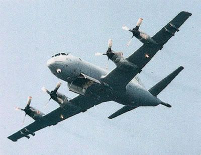
Image credit: Global Aircraft.
A P-3 Orion crew typically consists of the following members:
* Three pilots, designated 1P, who is the aircraft commander and makes the tactical decisions; 2P, who monitors the aircraft’s systems; and 3P, who is a new Orion pilot and comes straight from the Fleet Readiness Squadron;
* Two flight engineers;
* Tactical coordinator (TACCO);
* Navigator/communications operator;
* Two acoustic operators (Sensor 1, responsible for active sonobuoys, and Sensor 2, responsible for passive sonobuoys, although there is a lot of cross over);
* Non-acoustic operator (Sensor 3); and an
* In-flight tech/ordnance crewman.
Why three pilots? Flying at low level over the ocean for long periods of time, monitoring a myriad of instruments and maneuvering constantly to put the aircraft in a favourable position for the detection of submarines, is hard work. Three pilots are in fact probably the minimum necessary for most missions. Fortunately, the cockpit is spacious. During night missions, a curtain separates the cockpit from the remainder of the cabin, allowing the flight crew to concentrate on their instruments.
Moving toward the rear, the TACCO’s station just outside the cockpit on the left. He recieves information from the three sensor operators and passes it to the cockpit so that the pilots can position the aircraft advantageously for an attack or sonobuoy drop. The TACCO is responsible for search tactics and tactical control. His console is dominated by a large screen showing the locations of sonobuoys, surface contacts, and the aircraft, as well as possible submarine contacts.
Sonobuoy information used to be recorded on two 16 channel AQH-4 analog magnetic recorders, each weighing nearly 300 lbs and providing only two hours’ recording time, but this was replaced by an 80 lb AQH-13 system using Digital Tape Format (DTF) cassettes that offer four hours of recording time per cassette.
On the TACCO’s right hand side is the Navigator/Comms, who is responsible for all navigation and communications duties.
Further down on the right side sits Sensor 3, the operator who processes information gathered by the radar (the APS-137 is the most recent type), forward looking infra-red (FLIR), the MAD and ESM. His console has a large radar display for the APS-137, which has four modes: periscope; weather; surface search; and navigation; and can effectively track 32 contacts. Right above the radar display is the FLIR display.
Behind Sensor 3 on the left and seated facing “out” of the P-3 (all other crew members sit facing forward) are Sensors 1 and 2, who process sonobuoy data from the sonobuoys. All of the information received from the sonobuoys is channeled into the UYS-1 Single Advanced Signal Processor (SAPS). Although Sensor 1 is technically responsible for passive buoys and Sensor 2 for active types, both can process the information from either type. A maximum of 32 sonobuoys can be monitored simultaneously (it used to be only four on the original P-3A), but only if they are all passive. Returns from the buoys are displayed on a screen, looking much like a “green snow blizzard”. When not actively engaged in ASW efforts, both Sensors 1 and 2 act as observers looking out of the aircraft’s windows and as such, both are also qualified photographers.
The locations of sonobuoys dropped by the aircraft must be constantly updated, since getting a target bearing from a buoy is only useful if the correct location for the buoy is known. In order to correctly plot a buoy’s position for the benefit of the TACCO, it is necessary to take into consideration the aircraft’s altitude, air speed, and the wind characteristics. The drift of the sonobuoy is reported by an On Top Position Indicator (OTPI), which reports the information back to the aircraft. Information collected by the buoy, either from active (“pinging”) or passive acoustic means, is transmitted to the aircraft in the VHF band (over a number of channels). The TACCO uses the ASQ-114 digital computer, with its memory loaded with a large number of submarine acoustic profiles and radar and radio signals for ESM, to identify targets.
Halfway along the aircraft is the sonobuoy rack and chutes, with an observation position on either side of the fuselage. This is the domain of the In-flight Tech and Ordnance crew member, who is responsible for in-flight repairs of the electronics, and for preparing sonobuoys for drop. During the aircraft’s transit to the patrol area, he inserts the Cartridge Actuated Device (CAD, a pyrotechnic firing device that launches buoys from their tubes, leaving behind the smell of cordite and a little smoke) and “channelizes” (assigns VHF channels) the sonobuoys in their rack.
The P-3C can carry 84 sonobuoys, of which 48 are pre-loaded from the outside before takeoff and 36 are carried in the cabin. In the cabin there are three “A size” launch tubes and one larger “B size” tube (for use without cabin pressure).
Behind the sonobuoy rack area is the crew rest position and galley.
So how has the Orion’s mission changed since the Soviet submarine threat has all but vanished?
Turns out the P-3 Orion is more valuable than ever, but in a different role than traditional ASW and maritime patrol, as illustrated by the fact that it was responsible for shooting perhaps a couple dozen Standoff Land Attack Missiles (SLAMs) over the Balkans during Operation Allied Force in 1999 and during Operation Enduring Freedom in 2001; and as well, during Operation Iraqi Freedom in 2003, Orions were engaged in supporting the advance of ground forces toward Baghdad, warning them of enemy activity ahead, locating enemy armored vehicles at night, and making the initial detection of the burning oil fields at Ramallah; supporting US Navy SEAL and British Royal Marine commando operations to seize Iraqi oil terminals before they could be sabotaged; were involved in the rescue operation for captured soldier Pfc Jessica Lynch; aided in intercepting ships trying to smuggle oil out of Iraq; and provided targeting to a USAF AC-130 gunship so it could destroy some Iraqi patrol boats.
Submarine Self-Defense against Air Attack
How can a submarine defend itself from air attack?
Historically, or at least since the tide turned during the Battle of the Atlantic, a submarine’s only defense has been to “run silent, run deep”. But in any case, run. Gone are the days of the U-boat’s Turmumbau flak guns.
The idea of submarine self-defense against aircraft never went away, however. The Soviets, for example, have been known to equip their diesel-electric types, particularly the Kilo (Project 877/636) class, with shoulder launched, short range heat seeking missiles, due to concern that they might be caught on the surface. The launcher and missiles are typically stored in a watertight container located between the snorkel and the radio antenna masts in the sail. The earlier Type 877 had a SA-N-5 (Strela) launcher and 8 missiles, while the Type 636 has the more capable SA-N-8 (Igla-1M) launcher and six missiles.
There have also been several efforts aimed at coming up with a way of launching a missile from a submerged submarine against a hostile aircraft. For example, the American DARPA program of the late 1970s for a Self-Initiated Anti-aircraft Missile (SIAM). More recently, the German Navy looks to adopt the IDAS (Interactive Defence and Attack System for Submarines): a fibre optic guided adaptation of the air launched IRIS-T short range missile, which can be launched from a torpedo tube and is due to arm Germany’s Type 212 submarines from 2014.
The IDAS missile breaking the surface after launch from the Type 212 sub U-33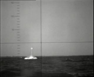
Image credit: Aviation Week.
D. ENDGAME: EVASION, DECOYS, AND COUNTERMEASURES
It goes without saying, of course, that a submarine’s best defense is to stay undetected. And if detected, a submarine hopes to break contact as soon as possible and disappear once more. You can’t kill what you can’t find, and all that.
However, once firmly discovered, a submariner’s life can become a frantic race for survival. (Many hours of Silent Hunter 3/4 have reinforced that point with me 😆 ). As with many other ASW technologies, the techniques and tools of evasion, decoys, and countermeasures have their origin in World War II.
1. Submarine Decoys and Countermeasures
From about 1942 onward, just as Germany beginning to lose its iron grip on the Battle of the Atlantic, the Kriegsmarine introduced the Pillenwerfer (or BOLD) decoy. This was a metal can or tube about four inches in diameter and filled with a alkaline metal (calcium or lithium) hydride. When released from a U-boat and exposed to seawater, a chemical reaction released large amounts of hydrogen that poured out of the container in thousands of gas bubbles and thereby, created a false sonar target. A hydrostatic valve held the device at a depth of about 100 feet, and permitted the effect to continue for about 20 to 25 minutes.
The principal limitation of Pillenwerfer, however, was that if an attacker could see both the stationary decoy and the moving submarine at the same time, it could differentiate between the two (the decoy lacking Doppler shift). Furthermore, the slow moving U-boats found it difficult to quietly slip away before the decoy expired.
A solution was found in a further German submarine decoy technology called Sieglinde. Powered by electric motors that allowed it to move at about 6 knots, as well as change depth, this decoy more accurately simulated a moving submarine. Used in combination with Pillenwerfer, this was a more effective method of allowing the real U-boat to escape.
In the post war period, the US Navy began work in earnest on developing a suite of submarine countermeasures, including acoustic intercept receivers which would automatically detect sonar signals, including the ping of actively homing torpedoes, over the full frequency range. Sonar jamming was also developed, much in the same way as electronic warfare is aimed against radars and radios, using both noise and deception (echo repeater) techniques. The most success has been obtained, however, in the field of expendable countermeasures.
In the modern era, a submarine facing an air dropped, acoustic homing torpedo has little opportunity to sneak away and must act quickly just to survive. An airborne lightweight torpedo may be dropped only a few hundred yards away, or less, and in many cases, will immediately go into active search and homing mode. Today’s submarines are therefore typically equipped with a comprehensive expendable countermeasures system that combines both decoys (i.e. acoustic jammers) and mobile submarine/target simulators.
The decoys or jammers are ordinarily accommodated within their own individual launch tubes, and are ejected by compressed air, in either a manual or automatic (computer controlled) mode.
The US Navy’s ADC (Acoustic Device Countermeasure) Mk 1, essentially an improved version of Pillenwerfer, was an expendable acoustic countermeasures device (an “ensonification bubbler”) running on a saltwater battery, and weighing about 19 kg. It was introduced in the early 1970s. It has been followed by electronic decoys that actively emit an acoustic signal as a counter to homing torpedoes, beginning with the ADC Mk 2. These use a small, shrouded propeller to permit the decoy to “hover” in the water at a pre-selected depth. The Mk 2 has been followed (predictably) by the Mk 3, Mk 4, and Mk 5, which offer increasingly advanced signal generation. The British Royal Navy’s submarine service, meanwhile, has used such decoys as the Type 2042 and Type 2066 Bandfish.
The Mk 57 Mobile Submarine Simulator (MOSS) is a 10 inch wide, mobile decoy that weighs about 1,000 lb and can only be launched through a torpedo tube rather than through a dedicated decoy launcher. Entering service in 1979, it was originally intended to protect ballistic missile submarines, with the Trident SSBNs carrying six decoys and the attack subs carrying four. And, because a MOSS might need to be launched at any time, one torpedo tube was usually kept empty and available. The MOSS has since been replaced by the six inch EX-10 Mobile Multi-function Device (MMD), which can be fired from a countermeasures tube. Soviet/Russian equivalents include the MG-74 and Berilly systems.
2. Surface Ship Decoys and Countermeasures
If an enemy submarine cannot be killed or avoided (including by such means as reducing one’s acoustic signature, as with Prairie Masker described in Part 2), then for the surface ship it becomes a matter of torpedo defense. This can include maneuvers to complicate a submarine’s fire control (such as the zig zag course taken by Allied convoys during WWII) and deployment of decoys and countermeasures.
The first of these was the British Foxer decoy of World War II, introduced in reply to the introduction by Germany’s U-boat force of the G7es (T-5 Zaunkoning) homing torpedo in late 1943. There was nothing terribly sophisticated by Foxer. It was an arrangement of hollow metal pipes with holes cut into them, which was then towed about 500 feet behind a host Allied ship. To an early generation passive acoustic seeker, the noise produced by water rushing through the holes, and by the pipes banging together, made for a more attractive target than the ship’s propellers.
The obvious disadvantage of Foxer, of course, was that constantly towing the decoy created more noise than might otherwise be produced by the ship (or the convoy it was escorting), thereby potentially attracting the attention of U-boats. After the war, the T.Mk 6 Fanfare was introduced, which more accurately simulated the noise of a ship’s propeller rather than just produce broadband noise.
The most widely deployed towed torpedo decoy since that time has been the SLQ-25 Nixie (or variants thereof), which first entered service in 1974 and introduced improved deceptive countermeasures. The decoy or “fish”, measuring about 37 inches long, six inches in diameter and weighing about 46 lb, is towed at the end of a 1,600 foot cable, and can receive the incoming torpedo’s active sonar pings, amplify them, and then return the signals to the torpedo to lure it away from the ship. As with towed array sonars, it is generally unwise to tow the decoy at high speeds. Typically two SLQ-25 decoys are ready to be deployed (or “streamed”), in case one is destroyed by a successfully decoyed torpedo.
SLQ-25 Nixie torpedo countermeasures equipment aboard the USS Iowa (BB-61)
Image credit: US DoD.
Some torpedoes aren’t easily decoyed by acoustic means – for example, the wake homers. For this reason, US Navy aircraft carriers can have a pipe lattice structure at their stern to produce a larger than normal wake: this reduces the effectiveness of torpedoes like the giant Russian Type 65 by forcing them to track back and forth across a much larger area, burning up valuable fuel (and thereby reducing their range) in the process.
Wake homing torpedo guidance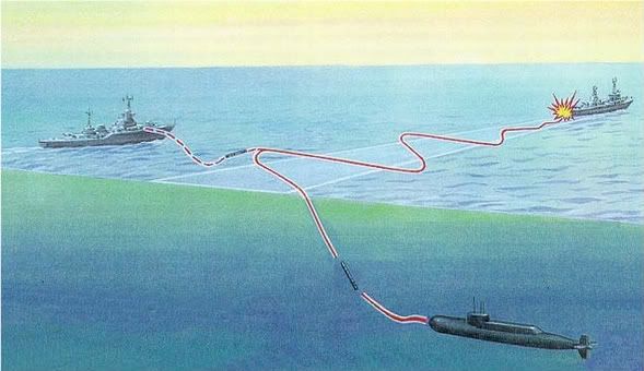
Image credit: US DoD
Other torpedo countermeasure programs have have sought to take advantage of the ubiquitous Mk 36 Super Rapid Blooming Offboard Chaff (SRBOC) launcher system fitted fleet wide in the US Navy, and widely exported to other NATO and allied navies. Ordinarily used to deploy chaff and infra-red decoys to defeat radar and anti-ship missiles, these 130mm launchers can now also use the Mk 13/14 Launched Expendable Acoustic Device (LEAD), a deploying a pattern of these decoys to seduce homing torpedoes.
3. The Hard Kill Option
In more recent years, navies have sought to develop a suite of integrated torpedo countermeasures that could automatically detect incoming torpedoes, deploy decoys or jammers to seduce or confuse them (the “soft kill” method), and if necessary, deploy anti-torpedo systems that could destroy them (the “hard kill” method). Examples of these efforts include the European SLAT (Systeme de Lutte Anti-Torpille) and the US-UK Surface Ship Torpedo Defense (SSTD) system.
The most difficult aspect of these kinds of programs has invariably been the hard kill element. One might wonder why it is tough to destroy an incoming torpedo. After all, we have developed the means to destroy supersonic sea skimming missiles, ballistic missiles, even satellites moving in orbit at 18,000 mph.
The answer: it is a fire control problem. Fire control depends on accurately predicting the position of an incoming weapon at the time of intercept by the defending projectile. That said, the detect to engage sequence for an underwater weapon is vastly more complex than that for airborne missiles. The ocean environment makes it significantly more difficult to receive and process data at a sufficiently high fidelity because of the speed at which information can be transferred underwater. Propagation speeds (radio frequency or infra-red signals in the air versus acoustic signals in the water) are nearly 200,000 times slower, so information is received significantly more slowly for a torpedo than for an airborne threat.
The development of an effective hard kill anti-torpedo system in the US Navy has been long and tortuous, evolving from the aforementioned US-UK SSTD program of late 1988 into what may eventually be achieved with the WSQ-11 Tripwire in fiscal year (FY) 2011. It is worthy of note, in comparison, that the Russian UDAV-1/RPK-5 Leevyen (Heavy Rain) or RBU-10000/12000, which combines a torpedo defense system of acoustic decoys, depth charges suspended by buoys, and explosives, has been around since 1989. The Israeli Scutter/Torbuster is another emerging system.
One unique system that has been under consideration came out of the DARPA Water Hammer mine countermeasures program in 2005. This would use explosives to generate a low frequency acoustic pulse in a sequence of shock tubes, which would in turn focus, amplify, and direct the pulse into the surrounding water over a narrow bearing, thereby creating a high pressure (around 2,000 psi) directional shock wave. This pulse could not only disrupt mines but would probably disrupt or destroy incoming torpedoes.
CONCLUSION
To quickly summarize, then, the ASW cycle requires detection of a submarine, location of its position, identification, targeting, and engagement. Its not at all as simple as that, of course, since each step in the process has its own quirks and is influenced by myriad factors, including the type of sensors at work, the nature of the target, and the tactics employed by both the hunter and the hunted.
Source references:
U.S. Submarines Since 1945, Norman Friedman, 1994.
Jane’s Navy International, November/December 1995.
Naval Institute Guide to World Naval Weapons Systems, 1997-98.
“What me worry? – The current state of surface ship torpedo defense”. Vining, P. USNI Proceedings, 1999.
The Third Battle: Innovation in the US Navy’s Silent Cold War Struggle with Soviet Submarines, Dr. Owen R. Cote Jr., March 2000.
Jane’s Information Group: August 1999; June 2003; September 2005.
Journal of Electronic Defense, March 2001.
ASW after the Cold War, Owen Cote and Harvey Sapolsky, MIT Security Studies Program, April 2001.
Air Forces Monthly, May 2001; December 2003.
Proceedings, June 2002.
National Defense, January 2003.
World of Defence, UDT, Issue No.2, 2004.
U.S. Destroyers, Norman Friedman, 2004.
Navy Times, August 2005.
SOSUS: The “Secret Weapon” of Undersea Surveillance, Edward C. Whitman, Undersea Warfare, Winter 2005.
Principles of Naval Weapon Systems, Craig Payne, 2006.
Not Ready for Retirement: The Sonobuoy Approaches Age 65, Holler et al., Sea Technology, November 2006.
Harpoon 3 Sonar Model, AGSI, 2007.
Proceedings, June 2007.
ES310, Introduction to Naval Weapons Engineering.
Ocean Talk, Naval Meteorology and Oceanography Command.
Gyrodyne Helicopters.
http://harpgamer.com/harpforum/index.php?/topic/3461-tactics-101-anti-submarine-warfare-asw-part-1/
http://harpgamer.com/harpforum/index.php?/topic/3527-tactics-101-anti-submarine-warfare-asw-part-2/
http://harpgamer.com/harpforum/index.php?/topic/3605-tactics-101-anti-submarine-warfare-part-3/
Part III
TACTICS 101: ANTI-SUBMARINE WARFARE: PART 3 – THE ASW CYCLE
In Part 1 of our discussion about ASW, we learned the basics of naval oceanography, and in large part, how sound behaves in the subsurface ocean environment.
In Part 2, we moved to a basic examination of the tools of anti-submarine warfare (ASW), the sensors, the platforms, and the weapons.
Now, in Part 3, we’ll examine the ASW cycle, the methodology of detecting, locating, and attacking submarines.
A. DETECTION, LOCATION AND TARGETING
1. Detection
Initial detection of a subsurface contact, whether by active or passive means, is your first clue that there is a submarine in the area, or in the old parlance, a POSSUB (Possible Submarine) report is generated.
For passive sonar, confirmation of submarine detection is often made through receiving and analyzing the lowest frequency sounds, such as propeller noises, and will give you a general idea that the target is in fact a submarine, rather than say, a biological or just “magma displacement”. It will not tell you which navy the submarine belongs to, or what type it is.
Broadband noise is produced by a target’s propulsion machinery, its propellers, the hull passing through the water, external fittings, etc. As a contact gets closer to the receiver, more and more information is gleaned as progressively higher frequency and lower strength sound becomes available, including narrowband sources. This combination of a ship or submarine’s self-noise, both narrowband and broadband, form its “acoustic signature” and can be exploited by to identify a contact as a submarine.
Initial detection by active sonar provides even less information, simply telling you that there is something there underwater. The determination of the identity of that “something” is a function of operator training and experience.
Direct Path
As discussed in Part 1, the direct path is the simplest acoustic propagation path and is essentially a straight line path between the sonar source and the target.
Due to the reduced opportunity for signal propagation loss and the fact that there is no reflection of the sound, a direct path sonar contact may be the easiest to obtain and analyse, but it also presents the shortest range passive detection opportunity (typically less than 10 nautical miles).
Because it is so short ranged, any surface ship obtaining a direct path detection of a submarine target is already in significant danger. It is extremely likely that the submarine has already been tracking the ship for some time, working a fire control solution, and is now approaching for the kill. It is the “oh, crap” detection scenario.
Bottom Bounce
With the bottom bounce technique, active sonar energy is directed towards the bottom. Steeply inclined sound ray paths are affected to a lesser degree than the shallower (in some cases, nearly horizontal) paths of other methods (e.g. surface duct, convergence zone, etc) and so there is less transmission loss and less potential for shadow zones.
Bottom bounce is only useful, however, where the ocean floor has a hard, flat surface (where you can get a good reflection) and its a poor choice where the bottom is rocky or soft mud (where sonar is dispersed by reverberations or absorbed). The Barents Sea, for example, has excellent conditions for bottom bounce sonar technique.
Because it typically involves the use of active sonar, however, bottom bounce carries a significant amount of risk in the ASW role and is a technique generally reserved for very specific scenarios where passive sonar simply isn’t sufficient.
Convergence Zone (CZ) Detections
As discussed in Part 1, convergence zones (CZ) are areas where refracted sound in deeper water can focus at the surface, typically at predictable intervals. The first CZ, for example, typically develops at about 30-33 nautical miles. The second CZ might form at 60-66 nm, a third at 90-99 nm, and so on.
The extent of CZ formation, or whether a CZ forms at all, is naturally dependent on whether sound can propagate far enough or deep enough, which in turn is dictated by environmental factors, notably water depth, temperature, etc.
In most cases, you are perhaps unlikely to get a detection beyond the first CZ. This is, under most conditions, a quite distant sonar contact in any event (keeping in mind, of course, that the CZ phenomenon can result in some pretty extraordinary sonar ranges). A contact would often have to be very loud and/or your passive sonar equipment very sensitive to achieve second and third CZ detections.
Also, a CZ detection will not usually provide any positional information on the target (i.e. you just get a bearing), negating the possibility of employing a long range ASW weapon against it. And, finally, a CZ detection tends to be a fleeting one. Once the target moves out of the CZ, or into a shadow zone, contact is often lost.
Sonobuoy Fields and Search Patterns
Using sonobuoys alone for an acoustic search is known as a “cold pattern”. Since sea temperature, pressure (a function of depth) and salinity all affect the way in which sound travels through the water, those factors need to be determined for an effective cold pattern.
The first sonobuoys dropped from a P-3 Orion might therefore be, for example, a SSQ-36 and a SSQ-57, in order to establish local ocean conditions. The SSQ-36 is a bathythermograph sonobuoy used to get a temperature profile, while the SSQ-57 is a passive, omnidirectional “calibrated collection” sonobuoy, used to acquire ambient noises roduced by marine life and other ocean sources.
Once local conditions have been established, the aircraft might move to laying a field of active and/or passive sonobuoys.
The layout of a sonobuoy field will depend on what kind of search pattern is employed. The following are some examples of search patterns, which could be used to sow sonobuoy fields or conduct a radar/FLIR/MAD search, each of which indicates a commence search pattern (CSP) point.
The parallel pattern is most desirable when the target is assumed equally likely to occupy any part of the search area.
Image credit: Journal of Simulation (2006) 1, 29-38.
The creeping line pattern is typically employed when the target is more likely to be in a particular end of the search area.
Image credit: Journal of Simulation (2006) 1, 29-38.
When the point of last contact is well known, or established within close limits, the square or sector search pattern is preferred. The square pattern is used when uniform coverage of the search area is desired.
Image credit: Journal of Simulation (2006) 1, 29-38.
The sector search pattern is used where the target is difficult to detect.
Image credit: Journal of Simulation (2006) 1, 29-38.
Finally, when a target is fast moving or when a strong current is present in the search area, the barrier patrol search pattern is preferred (its CSP is either starting point). This was the pattern used extensively during the actual Bay of Biscay U-boat war.
Image credit: Journal of Simulation (2006) 1, 29-38.
Although the greatest threat to a submarine is likely that posed by aircraft, it is by no means a sure thing that the aircraft will detect, locate, and successfully prosecute a submarine contact.
The sound of an aircraft coming close enough to attack (or the splashes from its dropped sonobuoys) can be detected by a submarine, particularly if the sub has a very sensitive passive sonar, such as a towed array.
And, since the submarine has better, more constant access to the ocean’s environmental conditions, it can use this information to exploit weaknesses in the aircraft’s sensor net. For example, by changing speed and direction, or by dropping below the thermal layer. Actively pinging sonobuoys can be mapped and avoided, or alternatively, hide directly beneath an active sonobuoy. This trick takes advantage of the fact that the active sonar pings move outward from the buoy like the rings from a tossed pebble, and so sitting underneath the buoy can shield the submarine to some extent.
2. Location and Identification
The next step is localizing the target. With active sonar, this is largely a simply exercise, but of course employing active sonar will almost always alert the enemy to your presence and so carries with it more than a little risk. Using passive sonar only, localization can still be accomplished by a number of means, including:
Target Motion Analysis (TMA)
An initial passive sonar contact typically provides only a bearing to the target, and tells you nothing about distance (range) or speed. The contact may be close by, creeping along at only 5 kt, or twice as distant, and moving at 10 kt.
Using only passive sonar, target motion analysis (TMA) is a mathematical process by which a contact’s course and range can be estimated using timed readings of the contact bearing and an estimate of its speed. Each estimate is (hopefully) more accurate than the one previous, and eventually the estimation will be accurate enough to reliably predict the next bearing. TMA is thus, essentially, an initial approximation of target range, course, and speed. The closer the ensuing predictions come to reality, the more likely it is that the approximation is an accurate one.
Suffice to say, any target whose bearing is changing rapidly is quite close and needs to be localised in a hurry. Conversely, a distant target will show almost no change in bearing over time. (The same can be said, of course, for target that is exactly parallel, but its bearing will change as you change course even slightly).
TMA is a tedious procedure, one that can consume a lot of time and create considerable frustration, but it is certainly more stealthy than energizing an active sonar and can eventually produce a suitable firing solution. Initially, TMA calculations involved only a paper plot, used to determine short range fire control, and later evolving into a computerised system using software target tracking that can project a target’s position ahead in time and be sufficently accurate to control wire guided weapons.
Limitations to the TMA technique include: contact must be maintained over a period of time; all contact bearings must be assumed to come from the same target over that period of time; and maneuvers must be built into own ship track in order to resolve ambiguities.
Beyond a certain range, of course, passive TMA techniques cannot reliably produce an accurate solution. For example, for convergence zone (CZ) detections, the only data typically available from passive sonar is a bearing. Range, course, and speed are practically impossible to determine. And, since a CZ contact is easily lost, the TMA solution clock would have to be reset and a new solution started from scratch each time.
LOFARGRAM
A Low Frequency Analysis and Ranging Record Gram (LOFARGRAM) plot can be generated where signal strength data can be gathered from non-directional passive sonobuoys.
The plot looks much like a waterfall display, and can be used be determine such identifying information as blade rate. This is a fairly complex exercise, however, and requires a detailed understanding of target signatures.
An example of a LOFARGRAM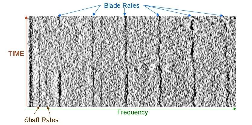
Image credit: Defence Science and Technology Laboratory (Dstl), UK Ministry of Defence.
Triangulation using DIFAR Sonobuoys
Here, each DIFAR buoy transmits a compass direction for each of its hydrophones and the operator can then determine which element on the buoy has the highest signal strength.
Target Identification
Although precise identification of the target may matter considerably less during wartime, when any unknown submarine contact found outside a recognized patrol area or transit lane may be assumed hostile, it is still of some value, especially when multiple targets present themselves. Identifying the contact can provide information about the threat it poses and help determine the application of rules of engagement (ROE) or an engagement priority. For example, identifying one of two submarine contacts as an Oscar II class SSGN, and the other as a Charlie class SSGN, may be convincing evidence of their threat priority.
At longer ranges, narrowband sources can be used to begin generating a picture of what the target might (or might not be). For example, during the earlier days of the Cold War, Soviet nuclear submarines could be broadly identified by their propulsion plants as follows:
Type 1 reactor plant: First generation nuclear subs, including the Hotel (Project 658) SSBN, Echo (Project 659/675) SSGN, and November (Project 627/645) SSN classes
Type 2: Victor (Project 671) SSN and Charlie (Project 670) SSGN classes
Type 3 (twinned Type 2 plants): Yankee (Project 667) and Delta (Project 667B) SSBN classes
Type 4: the Papa (Project 661) class SSGN
Type 5: the Alfa (Project 705) class SSN
Type 6: Sierra (Project 945) SSN, Oscar (Project 949) SSGN, and Akula (Project 971) SSN classes
Type 7: Typhoon (Project 941) class SSBN
More precise identification will require increasing analysis of a target’s noise signature and usually requires fairly close quarters proximity between the target and the sensor, so that your classification becomes more refined over time.
Improved sonar processing techniques now make it possible to detect and demodulate target noise to identify it by measuring its shaft or propeller blade rate (blade rate tonals). Also, as a note of interest, the more blades, the more likely the contact is a submarine (as commercial merchant ship propellers have only three or four blades, while warships often have five).
The twin shafts and propellers of the Arleigh Burke class Aegis destroyer USS Curtis Wilbur (DDG-54)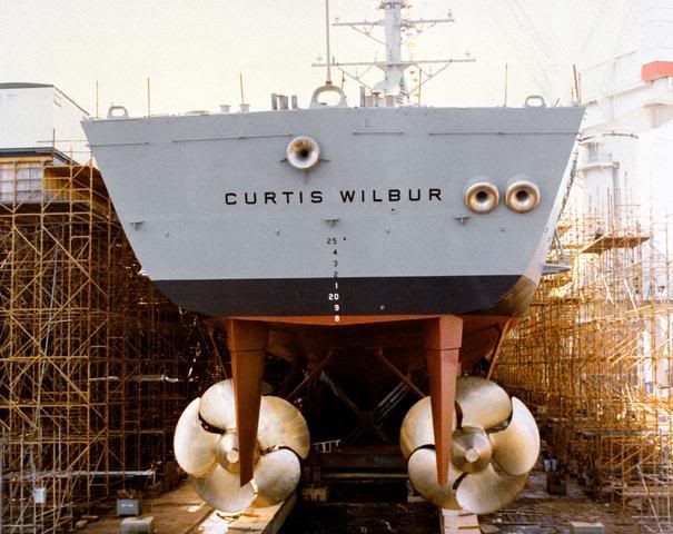
Image credit: Federation of American Scientists.
Many older Soviet/Russian nuclear powered submarines, such as the Yankee (Project 667), Delta (Project 667B), Papa (Project 661) classes, have five blades. So do some older diesels, including the Swedish Vastergotland (A17) class. The Soviet/Russian diesel-electric Kilo (Project 877) class has six, while the later Project 636 variant of the Kilo and the newest Lada (Project 677) class SSK both have seven blades.
Many other modern submarine designs employ seven blade propeller systems, including, for example, the Soviet/Russian Typhoon (Project 941) SSBN, the Victor (Project 671) SSN (though some of the Victor III (Project 671RTM) variant were unique in having two four-blade props mounted in tandem), and the Akula (Project 971) SSN; the US Navy’s Los Angeles (SSN-688) attack sub; the Chinese Type 039 (Song) and Type 039A (Yuan) class SSKs, and its Type 093 (Shang) SSN; and most newer European diesels, such as the Dutch Walrus SSK.
The 7 blade, skewed propellers of the Chinese Type 039 (Song) class SSK (this is the type that shadowed the US Navy’s carrier Kitty Hawk in October 2006, surfacing within 5 miles – uncomfortably close – apparently without having been detected).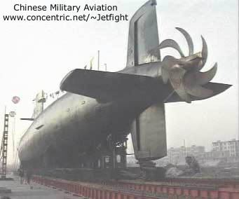
Image credit: Chinese Military Aviation.
It probably should be noted that blade noise among Soviet/Russian submarine types dropped dramatically after Japanese electronics company Toshiba and Norwegian company Kongsberg sold advanced milling machinery and control equipment to the USSR in the mid 1980s. (And, of course, the treachery of John Walker).
Listening to and recording a submarine’s unique sonar signature in peacetime can permit a navy to develop a library of what the other guy’s submarines sound like, so much so that it is eventually possible to identify a submarine contact not only by its class or type, but by name!
3. Targeting
The final step in the ASW cycle is targeting, that is, developing a sufficiently accurate picture of the submarine’s location and movements to mount an attack that has a high probability of success.
In the targeting phase, final localization of a submerged target is often accomplished using active sonar (either active sonobuoys, echo ranging, or an active dipping sonar), or magnetic anomaly detection (MAD) gear. An aircraft that has localised a target will typically drop a smoke flare to mark its position, and then come around for a second pass to drop the weapon.
Also, as discussed in Part 2, there are a number of other sensors typically available to an ASW aircraft that can provide both detection and location of a submarine contact when it is contact is surfaced, snorkeling or traveling at a shallow depth, including visual means, radar, and infra-red (IR).
Active means of detection are not usually exercised during encounters between opposing submarines, where an attacking submarine will typically want to maintain stealth throughout the engagement.
B. ENGAGEMENT
1. Airborne Attack
Aircraft, and in particular, helicopters, are a God send to the ASW surface ship. They provide a way to search for, detect, locate, engage and destroy submarine targets at ranges well beyond the ship’s own sensor envelope, while simultaneously avoiding the submarine’s own weaponry.
Modern ASW helicopters also have their own suite of dedicated sensors, including surface search radar (useful for spotting periscopes and snorkels), MAD gear, dipping sonar, and/or sonobuoys, not to mention the means to destroy a submarine with lightweight torpedoes or depth charges.
When used in concert with shipboard sensors, especially long range passive towed arrays, the helicopter is a formidable ASW tool, perhaps the most formidable of them all. Its ability to hover precisely over a contact, dip a sonar, or tend a sonobuoy field, and operate from just about any ship that can host a helipad, is a testament to its flexibility. About the only weaknesses of the helicopter are its limited endurance, relatively slow speed, and small payload, but these are just small factors in comparison.
Where helicopters are lacking, fixed wing maritime patrol aircraft (MPAs) make up for it. They invariably have long endurance, considerable payload, and better speed.
2. Stand-Off Attack
A stand off attack against a hostile submarine is always the preferable method of engagement, whether this is having your helo dump lightweight torpedoes from a position far ahead of the formation; sending an ASROC on its ballistic trajectory; or launching a heavyweight torpedo on a dogleg course that exploits wire guidance and approaches from a different bearing.
The advantage of stand off attack lies principally with being able to rapidly engage a submarine outside the effective range of its own weapons, and sometimes, beyond the effective range of its own sensors.
3. Close Range Attack
A close range engagement with a submarine is a dangerous affair, one that more often than not ends up with both the hunter and the hunted switching positions.
An attack from a position in the target’s baffles is one exception, in which case the attacker is already in the best possible position – the undersea equivalent of six o’clock high. If your opponent has a less capable passive sonar, maneuvering into an advantageous position is considerably easier and you may get much closer to him without being detected. If your passive sonar capabilties are about equal, however, then its really going to be quite a long, careful dance as you approach, followed by a frantic, desperate getaway.
The other close range option is a shipboard, “over the side” torpedo launch, in which case you are likely already in a worst case scenario. A hostile submarine has somehow managed to penetrate your screen and you are now trying to take last ditch, desperation measures to force him to maneuver by shooting your own torpedoes down the bearing of the contact (or worse, the bearing of an incoming weapon).
C. ANTI-SUBMARINE WARFARE (ASW) TACTICS
1. Tin Cans: The Surface Ship Sub Hunter
Since the noise of a surface ship formation (aka the “thundering herd”) produces a lot of ambient noise, and may drown out or mask the noise of an enemy submarine, or otherwise degrade own passive sonar performance, the surface ships with the best passive sonars (typically those equipped with towed array sonars) typically operate at some distance away from the main body of the formation.
This stand off distance is typically about 10 to 30 nautical miles (nm), and frequently, out to the range of the first convergence zone (CZ). Units with less capable passive gear (e.g. a hull sonar but no towed array) tend to be stationed closer to the main body, with those ships equipped with only active sonar the closest of all.
ASW escorts often employ “sprint and drift” tactics. The “sprint” involves racing ahead at high or flank speeds to the leading edge of their assigned patrol sector, and then slowing to creep speed (typically below 10 knots, or slower) to conduct the “drift”.
The sprint phase, of course, is noisy, but necessary in order to keep pace with the formation. The drift phase, however, cuts self-noise produced by revving engines, racing propeller screws, cavitation, and the noise of the hull passing through the water. In this fashion the ship can optimise the performance of its own passive sonar.
One might wonder why ASW ships bother to sprint at all, but rather, why not just creep from place to place to both optimise your own passive sonar and, at the same time, make the submarine’s job of finding you harder?
Well, firstly, of course, the naval surface ship group is typically on a timetable and more often than not, a strict one. HQ wants you to put that group on station in a particular place, establishing force presence, conducting sea control, or pounding the enemy, and the guy right above you in the pay scale no doubt wants it done yesterday. And since the primary objective of your surface group is rarely blue water ASW, there are other more pressing concerns that require you to move at best speed. Sprinting will allow your ASW ship to thus keep up with the “thundering herd”.
Secondly, there is truly an ASW method to the sprint and drift madness. Placing the most capable ASW assets on stations that are well removed from the noise of the main body, and in locations that either flank or are ahead of your group’s intended path, puts those assets in the best possible position to detect enemy submarines.
In most cases, diesel-electric submarines have little opportunity for engaging a surface group from the sides or rear. They simply lack the submerged speed and endurance to do so. And, while nuclear powered submarines have both the speed and the endurance, approaching a surface group from the sides or rear would necessitate high speed maneuvering.
Speed, as we have already discussed, is noisy and degrades own sonar performance. Simply put, in the subsurface battlefield, noise kills. Therefore, “nuke boats” will also try to place themselves in the path of an enemy surface group, again right where your ASW escorts hope to find them.
There is another, rather radical option for torpedo propulsion: rocket power. The advantage? Pure, unadulterated speed. B) The Soviets near monopolized the technology, starting with the introduction of the 70 knot RAT-52 anti-ship torpedo in 1953 (and copied by the Chinese as the Yu-2). They continued the trend with the APR-1, APR-2 and APR-3 rocket powered anti-sub lightweight torpedoes (though, in the case of the APR-3, the rocket motor drives a pumpjet), all capable of impressive speeds in the 62 to 65 knot range.
The most famous (or infamous) rocket powered torpedo is the Shkval (Squall) supercavitating projectile. Supercavitation is a phenomenon by which cavitation effects are exploited to create a bubble of gas under the water. An object within the gas bubble is able to escape the tremendous drag ordinarily created by traveling in water, and thereby move at high speed. By diverting some of its rocket exhaust through a nozzle on the nose, which helps to form the gas bubble, Shkval can achieve speeds approaching 200 knots. This eliminates the possibility of an acoustic homing head, leaving the weapon unguided, but as the Shkval can reach its maximum range of about 11,000 yards in less than two minutes, this may not matter.
VA-111 Shkval – note the opening at the nose for the rocket exhaust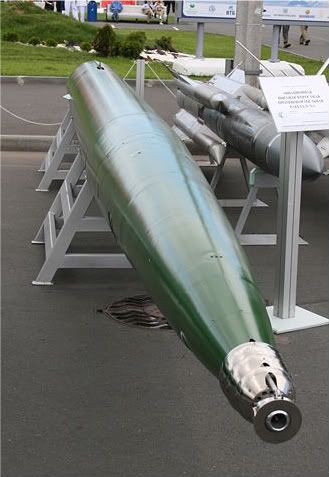
Image credit: One half 3544.
Guidance
The earliest “guided” torpedoes were straight running, relying only on the crew’s skill in using a slide rule and protractor, and gyroscopes in the torpedo, to send the weapon on what they hoped would be a collision course.
The German T4 or Falke, the first homing torpedo, was fitted with a passive acoustic homing device. Introduced in March 1943, it was quickly replaced by the T5 or G7s Zaunköning (Wren), which came into service that autumn. The T5 was faster, had superior range, and could use either magnetic or contact fuzing.
Again, however (as was the Kriegsmarine’s curse, it seems), these advances in ASW technology really came too late to have significant impact on the war, and by this time the Allies’ own technological pace was rapidly increasing. The Foxer towed acoustic decoy, for example, which was really just a noise maker that produced a more attractive target, condemned German passive homing torpedoes to a life of harmlessly circling behind their target until they ran out of fuel.
Passive sonar homing has traditionally been used as an anti-surface weapon. Although the Soviets had been pursuing the development of a domestic homing torpedo, that study had been interrupted by World War II. The capture of German T5 torpedoes got that project back on track, and by 1950, the first Soviet passive homer, the SAET-50, was in service. This was followed in 1961 by the electrically propelled SAET-60.
Active sonar homing has, on the other hand, been traditionally an anti-submarine weapon. The acquisition range of an active homing torpedo depends largely on its “ping rate” or “interrogation rate”, which is typically increased as the torpedo nears the target, in order to improve accuracy. The seeker’s aspect angle will define the band depth which the seeker can “see” at any given moment. Seekers with narrow depth bands tend to follow helical search patterns, while those with broader depth bands often use a snake like search pattern.
British Royal Navy Stingray lightweight torpedo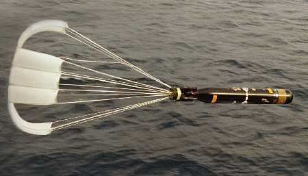
Image credit: Royal Navy.
Flow noise over the acoustic seeker head of a homing torpedo tends to interfere with its operation, but better signal processing and seeker dome shaping has brought improvements. Even so, active homing faces several obstacles. Near the surface, or in shallow water, reflections and reverbations can interfere with the seeker, and so active homing must rely on the Doppler effect to distinguish the real target from clutter. Considerable effort has been expended in recent years to improve active seeker performance in shallow littoral zones. Moreover, since active sonar can be heard at some distance, any submarine hearing an incoming torpedo can be expected to try to escape at high speed.
The generally accepted solution has been to combine active and passive homing, and moreover, to add wire guidance. This allows the torpedo’s guidance package to receive course correction commands, benefiting from the superior sensors of the launch platform to update the weapon on the target’s position. The guidance wire is dispensed from both the torpedo and the submarine to avoid stress on the wire due to their relative motion. Furthermore, with the advent of two-way or dual wire guidance, the torpedo becomes a self-propelled offboard sensor.
This way, a torpedo can be run out to the target’s vicinity under wire control and without alerting the target (except by its own propulsion noise). Upon reaching that area, the torpedo can carry out the terminal attack phase with its active sonar seeker. If the wire is broken (either accidentally or intentionally), the weapon can immediately switch to acoustic homing.
Wire guidance has typically been reserved for heavyweight torpedoes, with the exception of some Swedish and Russian lightweight torpedoes that use wire control to help overcome the difficult acoustic conditions found in the Baltic and other shallow water seas.
There is another, unique torpedo guidance option: wake homing. The Soviets have exploited wake homing for quite some time, firstly with its Type 53-57M in the mid 1960s, and it is only in recent years that the method has found its way into some Western torpedoes as an adjunct seeker capability (e.g. the French F17 Mod 2, Italian A.184 Mod 3 and Black Shark).
Wake homing uses an upward looking sonar beam to detect a ship’s wake boundaries. The control vanes are set to automatically turn the torpedo through a fixed angle each time the weapon crosses the wake, allowing it to follow a snake like track to the apex of the wake (the target). Since a ship’s wake extends for quite some distance (see the depth charge picture above for reference), it is a relatively simple matter for the seeker to determine its boundaries. One notable advantage of wake homing is that it is practically immune to countermeasures.
A further refinement of wake homing, cutely termed “wake nibbling”, seeks efficiencies by having the torpedo follow the boundaries of the wake rather than expend time (and fuel) crossing the wake.
The most well known wake homer is the Soviet Type 65-76 heavyweight torpedo, a monster 650mm weapon carrying a huge warhead capable of devastating the largest US Navy supercarriers. The Type 65-76 entered service with the first Project 671RT (Victor II) class attack submarine in 1972. It was retired in February 2002 after the tragic loss of the Kursk, an event widely blamed on an explosion related to the torpedo’s High Test Peroxide (HTP) fuel.
4. Stand-off ASW Missiles
As sonar performance steadily improved in the post World War II years, the US Navy perceived the need for a stand off weapon that could more closely match the range at which new sonars could detect enemy submarine targets. The objective was to be able to deliver an acoustic homing torpedo (or, alternatively, a nuclear warhead) to a point where the targeted submarine could not escape. This could be difficult, especially when engaging a submarine that was moving quickly, and so the process was largely dependent on an accurate prediction of where the target was going to be when the missile arrived. Absolutely precise accuracy was not required (particularly when using a nuke, of course), but it was necessary to drop the torpedo within acquisition range of its own acoustic seeker. What was needed was a quick reaction weapon with a short flight time.
Development of the RUR-5 ASROC (Anti-Submarine Rocket) began in the early 1950s, based on a relatively simple concept of using a solid rocket motor to deliver a Mk 44 homing torpedo or nuclear depth charge (the 10 kiloton W44) to a specific water entry point right above the enemy submarine. Range (up to 5 nautical miles) was determined by a timer set before launch, such that when the timer expired in flight, the rocket motor separated and the payload fell on a ballistic trajectory into the ocean.
Another program was soon launched to provide a similar weapon for underwater launch from submarines. Several technical problems delayed the program, but the UUM-44 SUBROC (Submarine Rocket) entered service with the USS Permit (SSN-594) in 1965. SUBROC was launched from a standard 21 inch torpedo tube, igniting its solid rocket motor once it safely cleared the submarine and breaching the surface. An inertial guidance system directed the missile toward the target location up to 30 nautical miles away, where, like ASROC, the motor separated from the payload. The only payload option for SUBROC was a 200 kiloton nuclear depth charge, leaving virtually no chance of escape for any enemy submarine within a radius of about 4 nautical miles.
In the early 1980s, the US Navy initiated the RUM-139 Vertical Launch ASROC (VLA) program to take advantage of the new Mk 41 Vertical Launch System being fitted in US Navy warships. However, another more promising program intervened – the RUM/UUM-125 Sea Lance – which promised a common successor to both ASROC and SUBROC. The Sea Lance would be capable of launch from either a submarine or surface ship, and would deliver either the new Mk 50 Barracuda Advanced Light Weight Torpedo (ALWT) to a range of 30 nm or a nuclear depth charge to 60 nm. Progress with the program was slow, and the end of the Cold War also spelled the end of Sea Lance.
RUR-5 ASROC launch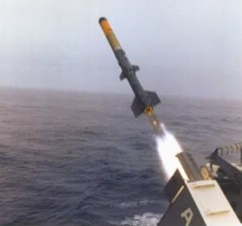
Image credit: David Schmitt.
Fortunately for the old reliant, this meant a revival of the RUM-139 VLA. It uses a new solid rocket booster and combines a digital autopilot with the inertial guidance system, improving maximum range to 12 nautical miles, making the missile more maneuverable, and permitting it to fly a lower altitude trajectory. Range is controlled in the usual manner, and the payload is the Mk 46 Mod 5A or Mod 5AS lightweight homing torpedo. (The originally plan to add the Mk 50 Barracuda was shelved, and instead the newest variant will use the Mk 54 Lightweight Hybrid Torpedo (LHT), which combines the guidance and warhead of the Mk 50 with the propulsion system of the Mk 46).
In the face of a growing Soviet submarine threat in the 1950s, NATO and Allied nations were quick to jump on the bandwagon.
The Marine Nationale (French Navy) introduced the Malafon in 1964, which could deliver the 533mm L4 acoustic homing torpedo to a distance of about 11 nm. A turntable launcher would slew to the target bearing and launch the missile at a fixed elevation of 15 degrees. Upon launch, two solid rocket boosters accelerated Malafon to about 450 knots before falling away, allowing the weapon to glide toward the target under radio control, dropping its torpedo payload in the usual manner about 800 meters from the target submarine. Malafon also had a secondary anti-ship attack capability. The Australian Ikara (from an Aborigine word for “throwing stick”), meanwhile, which entered service around 1966, delivered a Mk 46 acoustic homing torpedo to a range of nearly 10 nm.
The Soviet Union did not take long to recognize the inherent advantages of a stand off ASW missile, and developed its own version of ASROC. The 82R Vikhr (NATO Free Rocket Anti-Submarine, or FRAS-1) was essentially a navalised version of the FROG-7 (Free Rocket Over Ground) battlefield artillery rocket. Launched from the SUW-N-1 twin arm launcher, it was capable of delivering a 200 kiloton nuclear depth charge to a range of about 16.5 nm. The FRAS-1 was fitted to the Project 1123 (Moskva) and Project 1143 (Kiev) class aviation ships (except Admiral Gorshkov).
The RPK-3 Metel (Snowstorm) (NATO SS-N-14a/b Silex) appeared in 1970 aboard the new Project 1134A (NATO Kresta II) class guided missile cruiser. The 60R version carried a 5 kiloton nuclear depth charge, while the 70R carried a 450mm homing torpedo. Rocket propulsion and radio command guidance carried the weapon out to a maximum range of 28 nm, whereupon the payload was released.The SS-N-14 saw further variants developed in the early 1980s, including the 85R Metel-M (SS-N-14c), which carried a heavier 533mm homing torpedo; and the 85RU Rastrub (SS-N-14d), which returned to a lightweight (and more advanced) 400mm homing torpedo. Most interestingly, the SS-N-14d was capable of anti-ship attack, made possible by the addition of an IR guidance mode and a 185 kg warhead ahead of the torpedo payload.
The Soviets also did not fail to appreciate the utility of a submarine launched, stand off ASW missile. The RPK-2 Viyuga (Blizzard) (NATO SS-N-15 Starfish) introduced in or about 1972 performed the same way as the US Navy SUBROC, launched from a 21 inch torpedo tube, utilising a solid rocket motor and delivering a nuclear depth charge to a distance of about 25 nm.
Unlike the US Navy and the failed Sea Lance program, however, the Soviets have expanded their stand off ASW missile arsenal.
The 83R Vodopad and 84R Vodoley versions of the SS-N-15 (RPK-6), introduced in 1981, delivered a homing torpedo and nuclear depth charge, respectively, and moreover, could be launched from a surface ship. A further system, the SS-N-16 Stallion (RPK-7), takes advantage of the 650mm torpedo tube to achieve even greater range, at nearly 60 nm. The 86R Veter (SS-N-16a) and 88R Vsplesk (SS-N-16b) versions of the weapon deliver a homing torpedo and a nuclear depth charge, respectively. The latest Soviet stand off ASW weapon, the RPK-9 Medvedka (NATO SS-N-29), is intended for launch from small surface combatants, delivering a homing torpedo to a little over 12 nm.
Comparison of stand off and airborne ASW weapon delivery methods
Image credit: Brian Burnell.
In recent times, the US Navy has pursued a new concept in airborne stand off ASW, namely the High Altitude ASW Weapons Concept (HAAWC). (The effort was largely born out of a desire to reduce P-3 Orion airframe fatigue, and improve P-8 Poseidon endurance, by obviating the need to drop the torpedo at low altitude). HAAWC mates a low cost wing adaptor kit, nicknamed “LongShot”, with a lightweight torpedo and uses GPS based navigation to accurately deliver a torpedo to ranges of 50 nm. In May 2007, a HAAWC equipped Mk 54 torpedo was successfully deployed from a P-3 Orion flying at 8,000 feet.
5. Naval Mines
Mines, cheap and easily deployed, are perhaps the single most effective weapon available to a combatant who seeks to prevent the projection of naval power onto his shores. More than 50 nations currently possess naval mine inventories and are able to deploy more than 300 varieties of mines. Mine countermeasures (MCM), therefore, remain a critical enabler for maritime expeditionary forces. Like the weather, everyone likes to complain about mines but there’s not much we can do about it. If you think ASW is mind numbing, try MCM.
Mines can be offensive or defensive, that is, placed in enemy territorial waters to destroy or hamper the movement of enemy shipping, or alternatively, placed in defensive fields to protect friendly areas from intrusion by enemy shipping and to force them elsewhere. That being the case, mines can be either a deadly nuisance or a useful tool from an ASW point of view.
Mines can be classified in either of several ways:
(1) Method of delivery: aircraft laid, submarine laid, or surface laid;
(2) Method of deployment: bottom, moored, or drifting; and
(3) Method of actuation: contact, influence, controlled, or rising.
Method of Delivery
Whether offensive or defensive, any force intending to lay mines must prepare and maintain minefield plans for all geographic locations where it is intended to deploy mines. The cost and time necessary to remove mines (even your own) is many times more than the cost and time to deploy them. And, of course, hitting your own mines would be entirely unsatisfactory.
Just about any aircraft that can drop a simple iron bomb can also lay a mine. In fact, some mines are simply converted iron bombs. The US Navy Destructor (DST) series, introduced in the late 1960s, are a prime example. With a Mk 75 modification kit, any Mk 80 series iron bomb becomes a naval mine: the 2,000 lb Mk 84 becoming the Mk 41 DST, the 1,000 lb Mk 83 becoming the Mk 40 DST, and the 500 lb Mk 82 becoming the Mk 36 DST.
The newer US Navy Quickstrike series mines of the early 1980s work on the same principle, converting the 500 lb Mk 82 iron bomb into the Mk 62, the 1,000 lb Mk 83 into the Mk 63, and the 2,000 lb Mk 84 into the Mk 64. A fourth version, the Mk 65, uses a Mk 84 bomb with a thinner walled case and some other improvements.
The advantage of a submarine laid mine is related, unsurprisingly, to the submarine’s ability to reach waters usually inaccessible to other platforms, and to do so covertly.
The US Navy’s Mk 67 Submarine Launched Mobile Mine (SLMM), introduced in 1987, is essentially a modified Mk 37 torpedo that can be launched from a distance and delivered to a bottom laid deployment. Once deployed, it sits on the bottom until actuated by magnetic/seismic or magnetic/seismic/pressure sensors. It was retired in or about the year 2000. The Russian SMDM mine works on the same principle, using a 650mm heavyweight torpedo.
Many types of mines that can be laid from aircraft or submarines can also be laid from surface ships, much like depth charges, by rolling or sliding them off the ship from a rack. The advantage of laying mines in this manner is that a ship can typically carry and deploy much larger numbers of mines than an aircraft or sub. The principal disadvantage of surface mine laying is that the ship can only undertake the operation while in relative safety, making the task difficult to accomplish in enemy waters and thereby relegating surface laid mines largely to the defensive mission.
Many moored mines are laid from surface ships, including, for example, the Russian MAG and UGM types.
Method of Deployment
Drifting mines are perhaps the most feared, not because they’re particularly effective but rather because they tend to be indiscriminate. A drifting mine, carried anywhere by the wind and the currents, is just as liable to sink your own ship, or a non-combatant, as the enemy. Drifting contact mines were used on occasion during the world wars, but this limitation was eventually recognised. Sometimes a moored mine may break its cable and become a drifting mine, but modern types are usually equipped with electronics to sense the problem and deactivate or scuttle the mine.
The US Mk 19 and Russian APM (circa 1955) are examples of drifting contact mines.
A moored mine is connected to the seabed by a cable and anchor to keep it in place. The mine itself will float at a predetermined depth, the latter being determined by the tides in the area and more importantly, the intended target. Shallow moored mines are typically intended for use against surface ships, while deep moored mines seek submarine targets. Moored mines are unavailable, of course, where the water is too deep to result in effective deployment.
The US Navy’s Mk 56 and Mk 57 are examples of moored mines intended for the anti-submarine mission.
Early in the morning of 18 February 1991, the Iwo Jima class amphibious assault ship USS Tripoli (LPH 10) hit a moored contact mine that ripped a 16 x 20 foot hole in her hull below the waterline. The ship had been operating for some 11 hours in the previously undetected Iraqi minefield.
Bottom mines are generally used where the water is either very shallow or too deep for moored mines. As the name suggests, a bottom mine is deployed on the ocean floor and is typically difficult to detect and sweep. Bottom mines are useful in shallow waters where an enemy amphibious assault might be expected, or where you need a large warhead.
The Destructor and Quickstrike series mines described earlier are all examples of bottom mines, as is the Italian Manta which also haunted US Navy warships in the Persian Gulf during the first Gulf War. A few hours after the incident with Tripoli, the Bunker Hill class guided missile cruiser USS Princeton (CG 54) struck a Manta mine in about 16 meters of water, and about three seconds later, was hit by the sympathetic detonation of another about 350 yards away. The damage was substantial, including a cracked superstructure, severe deck buckling, and a damaged propeller shaft and rudder.
A Manta bottom mine just a few hours after deployment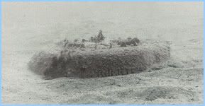
Image credit: SEI.
Method of Actuation
The earliest and simplest type of actuation was the contact mine, which in many respects typifies the traditional image of a naval mine. Early versions of the contact mine had mechanical detonators, but later evolved into chemical (such as the Hertz Horn, where contact with a target’s hull cracked a vial of acid that poured into a lead-acid battery) and electrical fuzes (where a copper wire attached to a buoy created a voltage and activated the detonator when in contact with a target’s hull).
Contact mines are increasingly rare in the modern era. The Russian AG, AGSB, and AMAG 1 are all examples of WWII era contact mines.
Influence mines are actuated by the “influence” of a target, that is, triggered by the presence of a ship or submarine itself, through the use of such sensors as magnetic, passive acoustic, or water pressure displacement. Early influence mines used simple magnetic sensors or broadband hydrophones. Advances in electronics and computer processing have seen the introduction of increasingly sophisticated sensors; for example, the introduction of “total field” magnetometers and narrowband passive sensors that can listen for certain acoustic signatures. These sophisticated systems permit a mine to be programmed to ignore all passing ships and submarines except for a very specific target.
When first introduced, pressure actuated mines were virtually immune to sweeping. There was no device that could simulate a ship’s pressure signature, except, well, a real ship. <_< The only protection against them was to move so slowly as to not cause a change in water pressure sufficient to set off the mines.
In practise, however, very few mines have been equipped with pressure actuation only, and in fact, most modern influence mines use multiple influence sensors as to avoid premature actuation by some natural phenomenon and to defeat simple countermeasures. (Most pressure mines, therefore, can be swept by using an acoustic noisemaker or magnetic field).
Examples of influence mines include the German DM 61 (G2), British Stonefish, and the Russian MDM-3/4/5/6 series of bottom mines.
Remotely controlled mines are typically found in defensive minefields, where the mines can be deactivated or detonated on command, usually by electrical signal from shore (usually when you can visually observe enemy targets), or switched over to normal (contact or influence) methods. Examples of controlled mines include the Chinese EM-57 and Swedish M/9 (GMI 600).
There is a fourth category of naval mine actuation, although in most cases it is a sub-variant of influence mines. The rising mine can lay very close to the ocean bottom, usually in moored fashion and in very deep water, and then launch a torpedo or projectile when a ship or submarine passes by. The influence sensor needs to have long range (1,000 feet or more), which generally necessitates a passive acoustic or magnetic system, because of the lag time between triggering the mine and the warhead or payload reaching the target.
The classic example of a sophisticated rising mine is the US Navy’s Mk 60 CAPTOR (Encapsulated Torpedo), which is a deep water (up to 3,000 ft) moored mine that uses “reliable acoustic path (RAP) sound propagation” as its influence method and the Mk 46 lightweight torpedo as its payload. It is strictly an ASW mine, ignoring surface ships and (reportedly) friendly submarines, and may be laid by air, ship, or submarine.
Mk 60 CAPTOR method of operation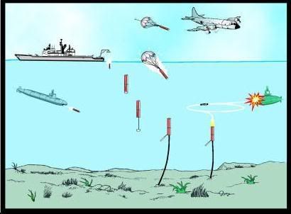
Image credit: Federation of American Scientists.
CONCLUSION
Hopefully this rather lengthy discussion has given you a useful foundation in the tools of anti-submarine warfare (ASW).
In Part 3 we’ll move to the ASW cycle, the specific methodology of detecting, locating, and attacking submarines.
Source references:
Jane’s Navy International, November/December 1995, November 1997.
Naval Institute Guide to World Naval Weapons Systems, 1997-98.
Military Parade, Stanislav Proshkin and Valery Marinin, 1998.
The Third Battle: Innovation in the US Navy’s Silent Cold War Struggle with Soviet Submarines, Dr. Owen R. Cote Jr., March 2000.
Jane’s Information Group: August 1999; June 2003; September 2005.
Journal of Electronic Defense, March 2001.
ASW after the Cold War, Owen Cote and Harvey Sapolsky, MIT Security Studies Program, April 2001.
Proceedings, June 2002.
National Defense, January 2003.
Undersea Dragons: China’s Maturing Submarine Force, Lyle Goldstein and William Murray, International Security, Spring 2004.
World of Defence, UDT, Issue No.2, 2004.
U.S. Destroyers, Norman Friedman, 2004.
Naval Institute Guide to the Ships and Aircraft of the US Fleet, Norman Polmar, 2005.
Navy Times, August 2005.
SOSUS: The “Secret Weapon” of Undersea Surveillance, Edward C. Whitman, Undersea Warfare, Winter 2005.
Principles of Naval Weapon Systems, Craig Payne, 2006.
Not Ready for Retirement: The Sonobuoy Approaches Age 65, Holler et al., Sea Technology, November 2006.
Harpoon 3 Sonar Model, AGSI, 2007.
Proceedings, June 2007.
ES310, Introduction to Naval Weapons Engineering.
Ocean Talk, Naval Meteorology and Oceanography Command.
Federation of American Scientists.
GlobalSecurity.org – Reliable Security Information
The U-boat Wars 1939-1945 (Kriegsmarine) and 1914-1918 (Kaiserliche Marine) and Allied Warships of WWII – uboat.net
Designation-Systems.Net
5. Electronic Surveillance Measures (ESM)
There are two sides to submarine electronic surveillance measures (ESM): firstly, as a means of self-defense, and secondly, as a means of targeting or situational awareness.
Typically a submarine has an omni-directional radar warning antenna atop the periscope, which functions much like aircraft’s radar warning receiver (RWR), and indeed, some submarine radar warners are just versions of airborne systems. For diesel-electric submarines, in particular, radar warning is vital since the submarine must spend considerable time either surfaced or snorkeling and therefore exposed to enemy radar.
During World War II, when submarines still hunted their prey on the surface, it became evident to the German Kriegsmarine that their U-boats were being detected by Allied airborne radar. The first basic RWR, the FuMB-1 Metox (FuMB, or Funkmess-Beobachtungs-Gerat, means “radar warning apparatus”), was rushed into service in mid 1942 in an effort to give U-boats adequate warning of the presence of Allied radar. However, it was eventually discovered that Metox itself emitted a signal that could be detected and tracked by the Allies, with the result that it was much a beacon as it was a warning device.
Several successors were developed and pressed into service, but the Germans found it difficult to field a reliable system that could accurately match Allied radar frequencies and provide more than a very short warning time (sometimes only one minute). By the time they had seemingly perfected the technology (with the FuMB-35 Athos), the Battle of the Atlantic was over.
Modern day submarines are still equipped with radar warning and direction finding (DF) systems, but these have grown significantly more complex, and have evolved into tools of electronic surveillance rather than simple warning devices. The attack submarines deployed by Western navies bear physical evidence of the importance being assigned to the electronic surveillance mission. The submarine’s sail houses the upper portion of each periscope, mast, and antenna. When a submarine extends these devices while at periscope depth (roughly 60 feet), its steadiness in the water and the degree to which the boat is affected by surface wave action, depends on how deep in the water the hull remains. With a tall sail, the submarine’s hull can remain deeper in the water and thus remain steadier.
However, sail height has a price. It creates considerable drag, increases flow noise, and is prone to a dangerous phenomenon called “snap roll”, in which the sub can unintentionally dive while attempting to execute a turn (because the sail acts like a plane). Because of these problems, there have been attempts over the years to reduce or eliminate the sail, but beginning with the Sturgeon (SSN-637) class, the US Navy actually enlarged the sail, specifically to expand electronic surveillance capabilities (a testament to the importance of the mission). The Soviets, meanwhile, have traditionally used considerably lower sail structures (presumably due to significantly less interest in using their submarines in the electronic surveillance mission).
Submarines that use active emitters while at periscope depth or when surfaced (such as the surface search radar or communications mast, the latter exploiting HF, VHF, UHF and SATCOM channels) are advertising their position to enemy assets that have the ability to detect or intercept those emissions, even if the submarine is not otherwise detectable by other traditional methods (sonar, radar, IR, MAD, or the good old Mark I human eyeball). This is because, just like sound waves, radio frequency (RF) waves travel much further (and can be intercepted much further) than the range at which they can effectively be used by the emitter.
Because of the risks associated with coming to a shallow or periscope depth to conduct communications, and the generally inhospitable relationship between salt water and most radio frequency communications, the US and Soviet navies explored alternate methods. Only extremely low frequencies (ELF) in the range of 3-100 Hz are able to penetrate to any appreciable distance under the ocean, and for many years, ELF was the principal means of long range covert communications with their deployed submarines. The US Navy used an ELF system in the 76 Hz range, while the Soviets had a 82 Hz system.
The ELF system had certain advantages: worldwide range, low power requirements (only a few watts), and the ability to communicate with submarines at deep depths. However, it also had certain, significant disadvantages: one way transmission (submarines were receive only), very slow data transmission and limited bandwidth (meaning a typical ELF message comprised only a short coded message), and multi-path distortion (the result of energy arriving at the receiver over more than one path). The end of the Cold War and the availability of many more communications options spelled the decline of the importance of ELF. In September 2004, the US Navy announced it was turning off its ELF transmitters at Clam Lake, in the Chequamegon National Forest, in northern Wisconsin, and in Upper Michigan’s Escanaba State Forest near Republic.
Extremely low frequency (ELF) concept of submarine communications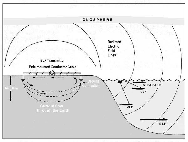
Image credit: R. Romero and V. Lehtoranta, 22 November 1999.
Submarines also sometimes use buoys to establish communications while remaining submerged. Examples in US Navy use include the BRC-6 XSTAT (Expendable Submarine Tactical Transceiver) for two-way UHF communications between a submarine and aircraft; the BRT-1 SLOT (Submarine Launched One-way Transmitter), which broadcasts a pre-recorded message of up to four minutes duration; the BRT-3/4/5 identification buoys; and the BRT-6, which transmits one-way UHF communications to a satellite.
5. Lasers
Lasers have long been a favorite subject of military related research, and its no surprise, then, that they also have application in undersea warfare.
In the 1980s, the US Defense Advanced Research Projects Agency (DARPA) studied the possibility of developing laser based communications between satellites and submerged submarines. The system would use complex blue-green lasers to accomplish this task, since the attenuation of light in sea water is minimized in the blue-green region of the electromagnetic (EM) spectrum. The technological challenge was steep, however, since the satellites would need to be fitted with a highly efficient, solid-state laser with a high power output, and the submarine receiver would need a filter to remove the background solar radiation that would otherwise interfere with their detection of the very faint laser signals. The project was eventually abandoned. (It is notable that optical data relay via satellite was eventually achieved and successfully deployed, as exemplified by ARTEMIS (Advanced Relay and Technology Mission Satellite) launched in 2001).
Blue-green lasers have since, however, found a niche in the mine countermeasures role, again due to their ability to penetrate water. The AES-1 ALMDS (Airborne Laser Mine Detection System), the first of which was fielded in 2007, uses a blue-green LIDAR (Light Detection And Ranging) laser to rapidly detect, localize, and classify near surface, moored and floating sea mines. Housed in a 9 foot long, 820 lb pod hung from a MH-60S helicopter, the laser images the entire near-surface volume of water that might potentially contain mines.
AES-1 ALMDS pod aboard MH-60S helicopter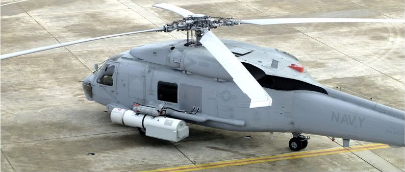
Image credit: Northrop Grumman.
C. ANTI-SUBMARINE WARFARE (ASW) WEAPONRY
1. Depth Charges
Perhaps the oldest anti-submarine weapon is the depth charge, developed during World War I as a relatively simple “barrel” of TNT detonated by a water pressure activated “pistol” at a selected depth. The first (and most basic) means of delivery was to simply roll the depth charges off the stern of a surface ship as it passed over the guesstimated location of the enemy submarine.
Scoring a direct hit with a depth charge was improbable, of course, but the shock of a nearby explosion could cause serious and accumulating damage, and did tremendous psychological damage to the crew of the submarine being subjected to the barrage. The slow speed and limited endurance of early submarines meant that their only means of defense was to conduct evasive maneuvers at the last possible moment and to try and get as deep as possible (a depth charge sinking above a deeply submerged submarine would take longer to reach its depth, thereby giving the submarine more time to move away). If a surface ship could catch a submarine in shallow water, however, depth charges were a cheap and effective means of damaging it or at least driving it off. (A kill was unlikely. The fact that U-427 is reported to have survived an onslaught of some 678 depth charges during an attack in April 1945, is a good illustration of the same).
Eventually depth charge projectors (like the British K-gun) were developed, which could hurl a depth charge out to the side of the ship, and when used in combination with stern racks, could lay a pattern of depth charges over an enemy submarine, hoping to bracket it.
An Allied destroyer dropping a pair of depth charges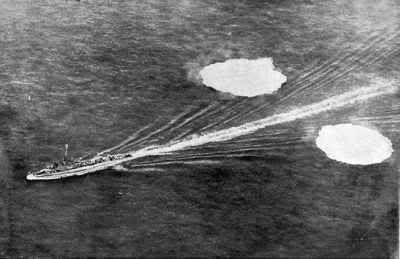
Image credit: Mary Bellis.
2. Ahead Thrown ASW Weapons
Ahead thrown ASW weapons fire a salvo of charges or bombs in a pattern over an enemy submarine’s position. The most famous, the Royal Navy’s Hedgehog system of World War II fame, fired a salvo of 24 bombs from a spigot mortar (essentially derived from a type of infantry trench mortar where the mortar launching tube is actually built into the tail of the bomb). Each bomb weighed about 65 lb and contained 30-35 lbs of explosives. The pattern, dropped ahead of the ship at ranges approaching 200 yards, could be either elliptical or circular in shape (depending on variant) and measured 120 to 200 feet across.
The principal advantages of Hedgehog over ordinary depth charges lay in the fact that the bombs were contact fuzed rather than working on a time or depth fuze; their smaller, streamlined shape allowed them to sink faster than depth charges (able to sink 200 feet within 30 seconds of launch); and the depth of the targeted submarine did not need to be known. Hedgehog rapidly achieved favor over the depth charge, and a much more impressive success rate, approaching 25 percent. A very similar American system, called Mousetrap, used four or eight rails for rocket propelled charges.
Hedgehog on the forecastle of the V&W class destroyer HMS Westcott (D47), 28 November 1945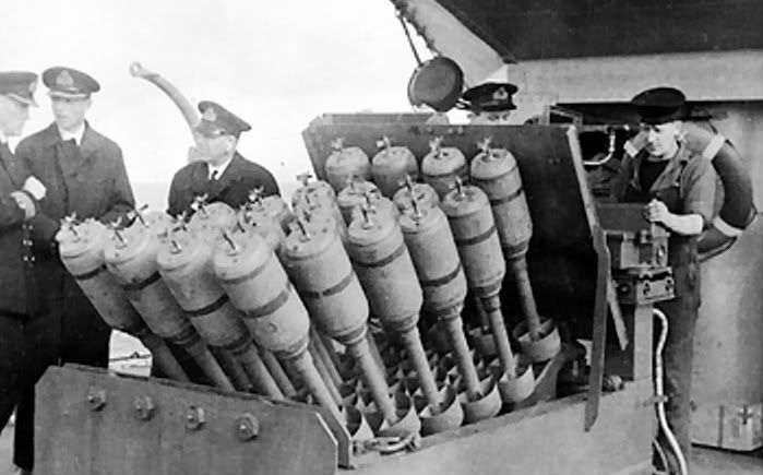
Image credit: IWM Collections, UK.
Ahead thrown weapons like Hedgehog and Mousetrap were so successful that the concept was immediately copied by the Soviets in the post war period, as the MBU and RBU series of ASW rocket launchers. The RBU series system, the latest of which is the RPK-8 variant of the RBU-6000, is still in use today despite the fact that it entered service nearly 50 years ago. The RPK-8 can launch a pattern of twelve 90R actively guided projectiles to a distance of over 2 nautical miles, each of which is equipped with a shaped charge. The system is believed to have secondary capability as a hard kill torpedo defense and anti-diver system.
RPK-8 launch from the Project 133.1 (Parchim) class ASW corvette Bashkartostan (MPK-228)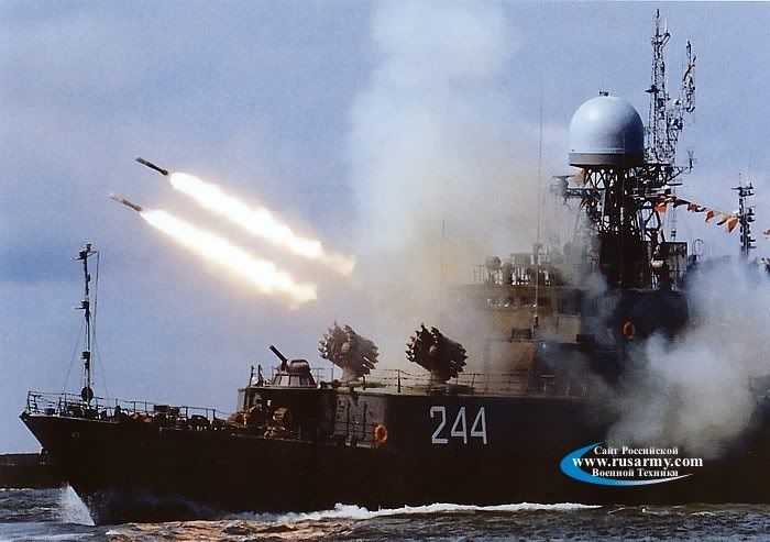
Image credit: : , , , ,
The UDAV-1/RPK-5 Leevyen (Heavy Rain) or RBU-10000/12000 series system optimises the torpedo defense role, creating an anti-torpedo barrier by launching rockets that deploy an outer layer of acoustic decoys, a middle layer of depth charges suspended by buoys, and an inner layer of explosives.
3. Torpedoes
The favoured, and most effective, ASW weapon remains the torpedo. The earliest “torpedoes” were probably better described as mines, demolition charges, or underwater booby traps, and the modern torpedo, a self-propelled underwater projectile, did not see widespread use until World War I. (Although the first victim of such a device is believed to have been the Turkish steamer Intibah on 16 January 1878). Torpedoes are generally divided into two categories or types:
(1) Heavyweight torpedoes, typically launched only from submarines (with the notable exception of some Soviet surface ship systems), usually 21 inches (533mm) in diameter (but sometimes larger, as with the 25.6 inch (650mm) Soviet Type 65), up to around 20 feet long, and may weigh several thousand pounds.
(2) Lightweight torpedoes, typically launched from aircraft and surface ships (again, with some exceptions), usually about 12.75 inches (324mm) in diameter (though Soviet types are often 16 inches), are less than 10 feet long, and weigh about 500 lbs.
Torpedoes are often also categorised by their method of guidance. More on that in just a bit.
Propulsion
The first truly successful torpedo designs used compressed air fed into a piston engine for propulsion, which was later modified to use a liquid fuel injected into an oxygen combustion chamber.
In the “wet heater” design, perhaps most popular among torpedoes of the two world wars, introducing water into the combustion chamber produced cooling and steam for even greater power (and speed). The principal drawback was that the steam left a visible trail of bubbles in the torpedo’s wake. (The German G7a torpedo was eventually relegated to use at night because of this).
Wakeless torpedoes came with the introduction of electrical (battery) power, but at the cost of reduced range and speed.
Electric propulsion is relatively cheap and is still used with some modern designs, though with more efficient, long lived batteries (often silver-oxide or magnesium types), such as the British Royal Navy’s Mk 24 Tigerfish or the German DM2 series. Electric propulsion also tends to have the advantage of being very quiet.
Other modern choices include gas turbines and swashplate piston engines powered by a high density (and often highly toxic) fuel, such as Otto Fuel II, for a so called “thermal” engine propulsion system.
As with submarines, torpedoes have sought to modify their propellers in an effort to improve propulsion and silencing. Pump jet propulsors encase the propellers in a shroud or duct, taking in water through an inlet in the front and pushing it out the rear, which both reduces noise and boosts speed.
Propulsor on Mk 50 Barracuda Advanced Light Weight Torpedo (ALWT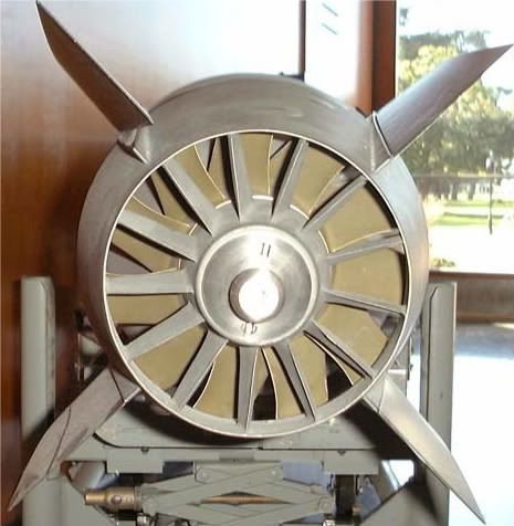
Image credit: US Navy.
Speed is of critical importance in a torpedo engagement. For early straight running torpedoes, it meant reducing the margin of error, where the target might maneuver at any time and ruin your firing solution. For modern undersea warfare, it means the ability to engage a fast nuclear powered submarine or surface warship, and the possibility of a rapid re-attack.
As a reliable rule of thumb, an ASW torpedo needs a 50 percent margin of superiority in speed over its target in order to assure that the target cannot escape once alerted to the attack.
Nuclear submarines were expected to achieve 30 kt speeds at 1,000 ft depths, thus creating the need for an ASW torpedo capable of at least 45 kt. A US Navy development program to achieve this for both light and heavyweight torpedoes was begun in 1956. (The later appearance of the Soviet Project 705 Lyra (NATO Alfa) class SSN was particularly alarming to NATO and repeated the process in some respects, spawning both the US Mk 48 ADCAP and British Spearfish torpedo programs).
In the first case, this effort resulted in the Mark 46 lightweight torpedo, which began deployment in 1965. In the latter case, requirements for a heavyweight torpedo were established in 1960, aiming for a 55 kt speed, a range of 35,000 yd, and a depth capability of 2,500 ft. In 1967, it was decided to make the heavy weapon also capable of anti-surface attack, which in turn mandated a larger warhead. In 1971, production of the Mark 48 began and the first examples were delivered in 1972, about 7 years after the first lightweight Mk 46 was delivered.
Many torpedo designs (of both today and yesteryear) have the option of trading range for speed. The German G7a (T1) steam driven torpedo of WWII was capable of an impressive 44 knots over about 6,500 yards, but at a leisurely 30 knots it could potentially achieve over 15,000 yards (though the chances of hitting anything at that distance was slim to none). A modern example, for comparison, would be the aforementioned Spearfish. It can reach 24,000 yards (almost 12 nm) at a blistering speed of 65 knots, or cruise to a distance of 50,000 yards (nearly 25 nm) at 29 knots.
Passive Sonobuoys
Passive sonobuoys have traditionally been the type of choice for open ocean ASW efforts by aircraft. By relying on passive sonar detection, a passive sonobuoy denies an enemy submarine the knowledge that it is being tracked or that an aircraft is searching for it.
The earliest passive LOFAR sonobuoys (such as the SSQ-23) provided only target detection with no indication of range or bearing. The CODAR (Correlation Detection And Ranging) method was developed to provide localization, wherein two pairs of sonobuoys were used to compare signal arrival times and resolve directional ambiguity. This was time consuming, however, and not particularly effective when the submarine went quiet. Another method was called Julie, more on that later.
The development of a LOFAR sonobuoy with directional capability, called a DIFAR (Directional Frequency Analysis and Ranging) buoy, combined omnidirectional hydrophones with compass information to provide target bearing.
The US Navy’s SSQ-53 DIFAR series of passive sonobuoys have directional detection capabilities, and offer selectable depths (between 90, 200, 400, and 1,000 feet, depending on type) and selectable endurance (between 0.5, 1, 2, 4 or 8 hours). Another example, the SSQ-77 VLAD (Vertical Line Array) combines the directional capability of the DIFAR with a vertical line array of omnidirectional hydrophones for improved tracking in a noisy, high traffic environment.
Active Sonobuoys
The acoustic pulse (ping) from an active sonobuoy more readily provides directional information (range and bearing) on a potential submarine target. Moreover, when two or more fixes are obtained, it is possible to establish the speed and course of the submarine. Active sonobuoys are typically deployed at deeper depths than passive buoys, and because of their power requirements, have typically shorter endurance.
The early SSQ-47 Ranger active sonobuoy produced a free running acoustic pulse every 10 seconds at one of six frequencies. It had a selectable depth, but a short life span, and provided only range information. It was replaced in due course by the SSQ-50 CASS (Command Activated Sonobuoy System), which pinged on command (in four fixed frequencies) from the launch platform rather than pinging continuously.
In the late 1970s, the US Navy introduced the SSQ-62 DICASS (Directional Command Activated Sonobuoy System) series active sonobuoys, with directional capability and frequency modulated (FM) sonar sweeps.
The proliferation of very quiet diesel-electric submarines among world navies (too quiet for effective use of passive sonobuoys) has led to increased interest in active sonobuoys and other shallow water detection techniques. This has included a return to the early concepts of broadband acoustics and echo ranging.
Explosive Echo Ranging
Acoustic propagation experiments conducted by Ewing and Worzel during WWII and the years thereafter used explosives as impulse sources to discover and exploit the Sound Fixing And Ranging (SOFAR) channel (now called the Deep Sound Channel). In 1960, for example, they dropped 100 kg depth charges off Perth, Australia, and discovered that the low frequency sounds could be heard by hydrophones near Bermuda some three and a half hours later.
Like CODAR, another operational mode saw the use of small explosive charges that could be detonated near passive sonobuoys to create a broadband acoustic pulse that would (hopefully) reflect off a nearby enemy submarine. This explosive echo ranging technique, called Julie, was introduced into the US Navy in 1956. The Soviets made extensive use of explosive echo ranging.
In the late 1960s, the Julie approach was replaced by active sonobuoys, but the use of explosives as an acoustic sensor continues today with the SSQ-110 Explosive Echo Ranging (EER) sonobuoy and the more recent SSQ-101 ADAR (Air Deployed Active Receiver) sonobuoy. The latter uses a multiple element planar hydrophone array to further improve detection capability in shallow littoral waters.
Special Purpose Sonobuoys
Specialized measurement sonobuoys can also be used to detect electric fields, magnetic anomalies, and bioluminescence (the light emitted by microscopic organisms disturbed by a passing submarine), as well as measuring important environmental parameters like water temperature, air temperature, barometric pressure, and wave height.
Although incapable of detecting submarines directly, measurement sonobuoys are critical to the ASW cycle. Prior to the deployment of detection sonobuoys, it is advisable to obtain a vertical temperature profile of the local ocean environment. This information can then direct the ASW operator as to what depths it might be useful to place detection sonobuoys.
The SSQ-36B bathythermograph (typically abbreviated BT), for example, is widely used by the US Navy for this purpose. It places a temperature probe at 800 meters depth and has an operating life of about 12 minutes. Submarines can also release bathythermograph probes (abbreviated XBT), which rise to the surface before then sinking and returning temperature data to the submarine. Obviously if the submarine is very deep, it may take awhile to start receiving data.
The SSQ-71 and SSQ-86 sonobuoys are used to establish two-way communications between an aircraft and a submarine.
7. SOSUS
The story of Project Caesar and SOSUS is perhaps one of the most significant and secretive stories in the history of the Cold War. SOSUS would become a key early warning asset against the perceived threat of Soviet submarines and in providing vital long range cueing information for open ocean ASW.
The culmination of several research efforts in the early 1950s on the topic of low frequency acoustic propagation, including Projects Hartwell, Jezebel and Michael (and including the findings of such researchers as Maurice Ewing, discussed earlier), was brought together to design, engineer, and eventually deploy a broad area surveillance system under the unclassified designation Project Caesar and the highly classified acronym SOSUS (Sound Surveillance System).
Simply described, SOSUS (designation FQQ-1/2/3/9) is comprised of passive hydrophone arrays hung vertically from the sides of underwater mountains. It takes advantage of the very long range propagation of low frequency noise in the deep sound channel (DSC) we described in Part 1, and “looks” into the deep ocean basins of the Atlantic. (It is not located at the chokepoints of the Greenland-Iceland-United Kingdom (GIUK) Gap, contrary to popular belief).
The low frequency noise emanating from a submarine, arriving at several different arrays, is triangulated and a SOSUS Probability Area (SPA) can be plotted as an ellipse ranging in size from 10 x 20 nautical miles (nm) up to 100 x 200 nm, depending on the range, angles, and numbers of arrays in contact with the target source.
By late 1957, several shore based monitoring stations, rather innocously termed “naval facilities” (or NAVFACs), were placed along the eastern seaboard of North America, forming a huge semi-circle from Barbados to Nova Scotia and opening toward the deep water west of the mid Atlantic Ridge. SOSUS was also extended into the Eastern Pacific, with NAVFACs spanning from California to Washington state, and with arrays later terminating at Guam, Midway, Adak (in the Aleutians), and at Hawaii. In 1959, another NAVFAC was established at Argentia, Newfoundland (less than a couple of hours from where I live), to monitor a number of shallow water arrays placed south of the Grand Banks. Others were strategically placed at locations like the North Cape (off northern Norway) and the Strait of Gibraltar.
SOSUS Naval Facilities (NAVFACs) in the Atlantic
Image credit: Edward C. Whitman
Though initially aimed at detecting snorkeling diesel-electrics, SOSUS proved even better at finding deep running nuclear powered submarines. The Soviets remained largely oblivious to the sensitivity and success of the SOSUS network until the criminal espionage of one John Walker Jr.
The end of the Cold War has seen the mothballing of much of the SOSUS network, with several monitoring stations closed (including, for example, the NAVFACs at Keflavik in Iceland, Adak, and Bermuda). The hydrophone arrays are still there, of course, but they have been placed in a stand-by status in which the data is available but not is no longer being continuously monitored.
A kind of “son of SOSUS” has since emerged in the Advanced Deployable System (ADS), a rapidly deployable net of broadband passive sensors that could be laid to detect submarines (particularly ultra quiet diesels), surface ships, and mine laying activities in shallow littoral waters. ADS is still in the development stage, and if procured and deployed, could be fitted to the Littoral Combat Ship (LCS).
8. SURTASS
While SOSUS is the fixed site portion of the Integrated Undersea Surveillance System (IUSS), the Surveillance Towed Array Sensor System (SURTASS) was developed in the early 1980s as the mobile, tactical element.
Several types of tactical auxiliary general ocean surveillance (T-AGOS) ships, namely the Stalwart, Victorious, and Impeccable classes, were deployed for the SURTASS mission, beginning in the mid 1980s. These ships employed the UQQ-2 passive sonar array, which was streamed for miles behind the ships and used for very long range submarine detection.
With the mothballing of the SOSUS network, SURTASS has been called upon to provide the undersea surveillance necessary to support regional conflicts and sea lane protection. Even SURTASS, however, has been the victim of a shift away from open ocean, deep water ASW toward the littoral, shallow water environment.
By 2004, only five of the US Navy’s 22 Cold War era T-AGOS ships continued to perform the ASW mission, comprising only one of the 18 original Stalwart class ships and all four Victorious class vessels, together with the ocean surveillance ship MV Cory Chouest.
Despite significant curtailment of the SURTASS fleet, however, the remaining assets have seen some significant upgrades in their capability, principally among them the Low Frequency Active (LFA) sonar array, and the TL-29A twin line array. Both are primarily aimed at detecting ultra quiet diesel-electric submarines.
The LFA is a powerful active sonar array system, designed to exploit low frequency acoustic propagation in the deep sound channel, and intended for use against targets too quiet to be detected by the passive system alone. Its extremely loud acoustic source is blamed for causing the deaths of numerous marine mammals during development and testing of the system, and has been the subject of considerable litigation. Presently installed only aboard the Cory Chouest, the LFA will eventually be fitted aboard the USNS Impeccable (T-AGOS 23).
The Low Frequency Active (LFA) system
Image credit: Pacific Whale Foundation (how’s that for irony).
The prototype TL-29A twin line array (which incorporates a pair of arrays towed side by side) is aimed at use in the littoral zone. It was tested during 1996 in a variety of world locations, with positive results, and was certified for deployment in November 2005. It is reportedly far superior to any other shallow water passive towed array system previously employed. Six TL-29A systems will support SURTASS vessels operating in the Western Pacific.
C. NON-ACOUSTIC DETECTION
1. Visual Detection
Submarines operating at or near the surface are extremely vulnerable to visual detection. Anything that protrudes above the surface, such as a periscope, antenna, or mast will leave a significant wake if the submarine is moving at any speed over a few knots. And, since depth control and steerage is quite difficult at low speeds, it is not uncommon for submarines to be traveling at least 4 or 5 knots just below the surface.
The periscope (for example) will create a wake, called “feather”, which is quite visible, and will also leave a remnant of its passage, called a “scar”. The scar is a long streak of foam or bubbles left behind after the object passes. The feather may be just a few meters, but the scar may be tens of meters long. Either may be visible for up to 10 miles, and are easily spotted by low flying aircraft in the vicinity.
Periscopes and other protuding masts and antennas are also often painted in dark or camouflage colors to reduce their visibility.
If the water is especially clear, the submarine hull or its shadow may be visible for a few hundred feet under water, but is usually not distinguishable unless the water is shallow with a light colored bottom (like white sand).
The vulnerability of the submarine at shallow depth visibly demonstrated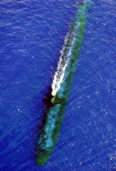
2. Radar
As their radar cross section (RCS) is generally very small, exposed periscopes and masts cannot usually be detected by ordinary surface search radars. Furthermore, the interference from sea clutter (e.g. waves) near the target will generally obscure it.
To be effective against a periscope or mast, a radar needs to have high resolution (both in range and bearing). Inverse synthetic aperture radar (ISAR) systems, such as the Raytheon APS-137B(V)5 set fitted to the P-3C Orion AIP variant, have proven very effective against submarine periscopes and masts.
Traditional submarine periscopes, masts, and antennas have been of the hull penetrating type, i.e. a column or pole of a length that typically extends the vertical length of the sail and the diameter of the submarine. New technology, however, will use non-hull penetrating systems by exploiting COTS advances in photonics (especially fibre optics). In addition to eliminating an opening in the pressure hull (always a good idea), eliminating the periscope column will potentially permit submarine designers to build longer, flatter sails than was previously possible, thereby improving hydrodynamic performance.
Taking advantage of this technology, the US Navy’s Virginia (SSN-774) class attack submarines have the Universal Modular Mast (UMM) – eight of them, in fact. Two will house a photonics sensor package, with high resolution color CCD TV, monochrome HDTV, thermal imager, eye safe laser rangefinder, ESM sensor, and a communications and GPS receiver. Two more will have high data rate satcom antennas.
Some synthetic aperture radars have also demonstrated the capability to detect the presence of a submarine by the change in the surface water height as it passes, known as the “Bernoulli hump”. This effect is greatest when the submarine is at shallow depth and moving rapidly. These is not a real time asset, however, since the necessary signal processing requires significant computing power and may take several hours to complete. Also, few submarine commanders would be so silly as to cruise at speed just below the surface in any situation where stealth was a priority (and it most often is).
3. Infra-red (IR) Detection
Submarines are vulnerable to passive infra-red (IR) detection when they are snorkeling, since the diesel exhaust is released close to the surface (as it must be because of the back pressure limitation). The exhaust gases give off a sufficiently strong IR signature as to be detectable. However, this is only useful if the submarine is snorkeling, which is only a few hours a day for diesel-electric submarines. Periscopes and masts are also susceptible to IR detection, though much less so than diesel exhaust.
Factors which play to the favor of the submarine, and limit the usefulness of IR sensors, include bad weather and high humidity levels, which reduce the effective range of an IR sensor.
Modern naval helicopters and maritime patrol aircraft are often equipped with forward looking IR (FLIR) systems, not just because they are useful tools for spotting submarines, but make for excellent aids in detecting, classifying and identifying surface ships as well. More recently, the FLIR systems of maritime patrol aircraft, such as the P-3 Orion, have proven useful in the overland reconnaissance mission.
4. Magnetic Anomaly Detection (MAD)
Magnetic anomaly detection (MAD) systems use ionized noble gas (such as helium) to measure changes in the Earth’s magnetic field due to the presence of a large amount of ferrous material found in most submarines. While ionized, the atoms in the gas are aligned, but when they pass by a localized magnetic disturbance (that pesky submarine), they change their alignment. This change in alignment is measurable, and can be recorded and displayed on a scrolling paper loop like an electrocardiogram (ECG) monitor or seismometer.
MAD gear is typically mounted aboard fixed wing aircraft and helicopters, and will indicate the presence of a ferrous metallic object when the aircraft overflies it.
MAD detection only works if the submarine is relatively shallow, and therefore is not a great long range detection system, being effective to within about 1,000 to 2,000 feet of the aircraft’s path. It can however, provide a precise location of the submarine of sufficient accuracy to permit weapons delivery, which is its main use.
ASQ-81 MAD system in the tail boom or “stinger” of a P-3C Orion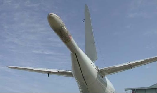


 Sign In