Curious claim. 😮
The F-86, the first one with a transonic wing, axial-engine and pressure suit built in numbers. 😉
And which one was the better fighter, the more agile and more powerfully armed? the MiG-15 well flown was always the better fighter. and if you do not believe it watch this video from an american perpective
http://au.youtube.com/watch?v=lT_PhJ7jBzw&feature=related
http://au.youtube.com/watch?v=YnZs0GDsdSM&feature=related
these are in my opinion the most influentail aircrft in History after 1939:
P-51: because it was the best piston fighter, it had a very advanced wing airfoil profile, bubble canopy and was a long range fighter.
Me-262:first jet ever operational fighter with swept wing.
MiG-15:it broke with piston style fuselage arragement of early La-15s MiG-9s or Panthers and adapted a central nose inlet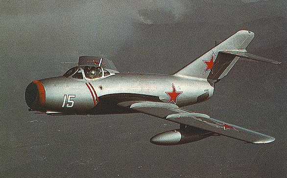
Mirage III:it broke with the straight wing and included an advanced inlet system, its wing became the ultimate delta wing
F-111:it influenced all the following swing wing fighters, from the MiG-23 to the F-14.
AJ-37:its canard layout has been taken since then by the Kfir, Rafale, Gripen, Lavi, J-10
F-15:Its inlets and booms have influenced most 1980s fighters, we could say the MiG-25 was its real forefather but the MiG-25 never was designed like a fighter, the A-5 was similar but still had a vestigial fuselage, no bubble canopy and no 9g capability and it was basicly a bomber.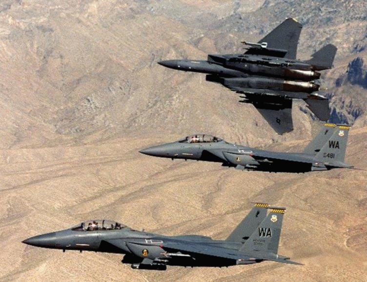
F-16:Its ventral inlet has influenced most designs since 1974 e.g J-10 Eurofighter MiG-29, Su-27 as well as its fuselage wing blending.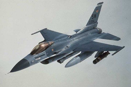
F-22:ultimate stealth fighter

Some people might not agree might say the F-92, F-102 and F-106 were the true forefathers of delta wings but these aircraft never featured an excellent design with an excellent combat record.
The F-15 and F-16 basicly were the real inspiration for the Mig-29 and Su-27 and the F-16`s design basicly was taken by the Eurofighter and J-10.
In fact basicly all modern fighters are derivatives of the F-16, F-15 and Viggen
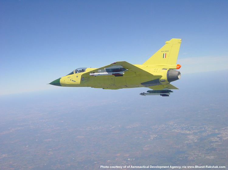
The article posted by me has a frontal photo of N-Tejas, on which LEVCONs are not clear. A clearer photo of the same is seen in this photo from DefExpo 2004. Again, the plan of addition and various photos of addition of LEVCONs on N-Tejas has been well known since 5-6 years now at least, whereas you may have known about it now only, in the course of this discussion.
As repeated earlier, terminology may not matter in this case as LEVCON and Apex fences are not recognized terms in standard aviation, because they are the particular proposals by individual organizations only.
The above is inaccurate. That LEVCON is a slat is a misconception, because official and unofficial publications clearly distinguish between the LEVCONs and present slats. Thus, as per as per the article “Radiance of Tejas”, mention that and I quote, “No such feature exists on any aircraft in the world”, end quote. Slats may be found on other fighter aircraft also, but not LEVCONs.
Please note that slats are not the equivalent of canards, whereas LEVCONs were supplanted after canards were removed from the Tejas.
Now, LEVCONs differ from slats thus :- As per the same article and as seen in the photo posted above, LEVCONs are not placed above or under the wing’s leading edge like slats, but are fully outside of the edge. Also more importantly, unlike slats LEVCONs will be under the pilot’s control and will have a separate computer to operate the same. Globally, slats in fighter planes are not under pilot’s control.
As per articles from acig.org and “Radiance of Tejas” posted earlier, LEVCONs will not only be used during landings, but also to increase controllability at high AoA and optimal use of instability.
Reference :-
Abhimanyu
LEVCONs are like slats however they have a slight difference and its the angle they can inflect that at negative inflections is really high 30 deg, the F-16 barely gets -2 deg up to my knowledge and do not know if other fighters can get negative inflections, so as such the LEVCONs are different to a regular slat at least to the F-16`s.
Now negative inflections must reduce camber and i guess are to stall in one way the wing or change the aerodynamic center of preasure over the wing, but in reality i do not know.
Now the LEVCON does allow better landing capabilities as the canards used on the Su-33 and in that you are right.
however there are facts that at least at this moment without more papers suggest the Canards still holds more advantages at supersonic speeds in terms of longitudinal stability.
Canards also use different methods to achieve vortex suction over the wing
Wing lift can be increased by using these techniques:1.
Increasing the wing area.2.Increasing the wing camber.3.Delaying the flow separation.Various combinations of these techniques are employed to produce the high lift coefficients required for takeoff and landing tasks. Typical lift augmentation designs employ leading and trailing edge flaps and a variety of BLC schemes including slots, slats, suction and blowing, and the use of vortices.
The relative benefit of each particular technique depends upon the lift characteristics of the wing on which it’s used. For example, a trailing edge flap on a propeller airplane with a straight wing might increase CL max three times as much as the same flap on a jet with a swept wing.
TRAILING EDGE FLAPS Trailing edge flaps are employed to change the effective wing camber. They normally affect the aft 15% to 20% of the chord. The most common types of trailing edge flaps are shown in figure 3.6.
FIXED WING PERFORMANCE3.12 Basic sectio Plain Split Slotted Fowler Figure 3.6
COMMON TRAILING EDGE FLAPSThe wing-flap combination behaves like a different wing, with characteristics dependent upon the design of the flap system. The plain flap is simply a hinged aft portion of the cross section of the wing, as used in the T-38. The split flap is a flat plate deflected from the lower surface of the wing, as in the TA-4. Slotted flaps direct high energy air over the upper flap surfaces to delay separation, as in the F-18 and U-21. Fowler flaps are slotted flaps which translate aft as they deflect to increase both the area of the wing and the camber, as in the T-2 and P-3. The relative effectiveness of the various types of trailingedge flaps is shown in figure 3.7.
STALL SPEED DETERMINATION 3.13 Basic section Plain Split Slotted Fowler Lift Coefficient CL Angle of Attack – degα Figure 3.7
LIFT CHARACTERISTICS OF TRAILING EDGE FLAPS
All types provide a significant increase in CL max, without altering the lift curve slope. An added benefit is the reduction in the α for CL max, which helps the field of view over the nose at high lift conditions and reduces the potential for geometric limitations due to excessive α during takeoff and landing.3.3.5.3 BOUNDARY LAYER CONTROL Lift enhancement can be achieved by delaying the airflow separation over the wing surface. The boundary layer can be manipulated by airfoils or other surfaces installed alongthe wing leading edge. In addition, suction or blowing techniques can be employed at various locations on the wing to control or energize the boundary layer. Vortices are also employed to energize the boundary layer and delay airflow separation until a higher α. Different types of BLC are discussed in the following sections.
——————————————————————————–
Page 24
FIXED WING PERFORMANCE3.143.3.5.3.1
LEADING EDGE DEVICES
Leading edge devices are designed primarily to delay the flow separation until a higher α is reached. Some common leading edge devices are shown in figure 3.8. Drooped leading edge Movable slat Krüger flap Figure 3.8 SAMPLE LEADING EDGE DEVICES The lift provided from the leading edge surface is negligible; however, by helping the flow stay attached to the wing, flight at higher α is possible. An increase in CL max is realized, corresponding to the lift resulting from the additional α available as shown infigure 3.9.
STALL SPEED DETERMINATION 3.15 Basic section Droop, slat, or Krüger flap Angle of Attack – deg α Lift Coefficient CL Figure 3.9 LEADING EDGE DEVICE EFFECTS Since the α for CL max may be excessively high, leading edge devices and slots are invariably used in conjunction with trailing edge flaps (except in delta wings) in order to reduce the α to values acceptable for take off and landing tasks
.3.3.5.3.2 BLOWING AND SUCTION BLC can also involve various blowing or suction techniques. The concept is to prevent the stagnation of the boundary layer by either sucking it from the upper surface or energizing it, usually with engine bleed air. If BLC is employed on the leading edge, the effect is similar to a leading edge device. The energized flow keeps the boundary layer attached, allowing flight at higher α. If the high energy air is directed over the main part ofthe wing or a trailing edge flap (a blown wing or flap), the effect is similar to adding a trailing edge device. In either application if engine bleed air is used, the increase in lift is proportional to thrust .3.3.5.3.3 VORTEX LIFT Vortices can be used to keep the flow attached at extremely high α. Strakes in the F-16 and leading edge extensions in the F-18 are used to generate powerful vortices at high α. These vortices maintain high energy flow over the wing and make dramatic lift
FIXED WING PERFORMANCE 3.16 improvements.
Canard surfaces can be used to produce powerful vortices for lift as well as pitching moments for control, as in the Gripen, Rafale, European fighter aircraft, and X-31 designs.3.3.6 FACTORS AFFECTING CL MAX3.3.6.1 LIFT FORCES To specify the airplane’s maximum lift coefficient, it is necessary to examine the forces which contribute to lift. Consider the airplane in a glide as depicted in figure 3.10.Horizon Relative wind WαjD LaeroγTG ατTG sin αj Figure 3.10 AIRPLANE IN STEADY GLIDE Where: α Angle of attack deg α jThrust angle deg D Drag l bγFlight path angle deg Laero Aerodynamic lift lb τInclination of the thrust axis with respect to the chord line deg TGGross thrustlbWWeightlb.
http://www.aviation.org.uk/docs/flighttest.navair.navy.milunrestricted-FTM108/c3.pdf

ask your self why leading edge slats and trailing edge flaps can not be used simultaneously in an aircraft like the LCA?
LEADING EDGE DEVICE EFFECTS Since the α for CL max may be excessively high, leading edge devices and slots are invariably used in conjunction with trailing edge flaps (except in delta wings) in order to reduce the α to values acceptable for take off and landing tasks
here is the answer

In the airplane’s normal range of flight attitudes, if the angle of attack is increased, the center of pressure moves forward; and if decreased, it moves rearward. Since the center of gravity is fixed at one point, it is evident that as the angle of attack increases, the center of lift (CL) moves ahead of the center of gravity, creating a force which tends to raise the nose of the airplane or tends to increase the angle of attack still more. On the other hand, if the angle of attack is decreased, the center of lift (CL) moves aft and tends to decrease the angle a greater amount. It is seen then, that the ordinary airfoil is inherently unstable, and that an auxiliary device, such as the horizontal tail surface, must be added to make the airplane balance longitudinally.
The balance of an airplane in flight depends, therefore, on the relative position of the center of gravity (CG) and the center of pressure (CP) of the airfoil. Experience has shown that an airplane with the centerof gravity in the vicinity of 20 percent of the wing chord can be made to balance and fly satisfactorily.
http://americanflyerslongisland.net/aviationlibrary/pilots_handbook/chapter_2.htm
That is the reason the F-16XL and LCA have leading edge notches to reduce pitch up momentum and probably the LEVCON also dampens the pitch up momentum
It actually says the exact opposite of what you have been blathering about in the thread.. it in fact supports the point that without canards, the LCA does fine. Ouch!!!
My pride flows from my professional qualifications and the work that I do. You might try a similar approach. Would help you.
Or try professional help. Clearly you have issues. Picking stupid fights on the internet accusing everyone else of being “proud” of being “blind” and this and that only testifies to your inferiority complex. Perhaps you are seeking to compensate for something?
While you have my sympathies for whatever is your problem, I cannot afford to waste my time and energy on your stuff beyond a point.
It actually shows you have been making silly comments all the while and wasting our time since ADA says exactly the opposite of what you have been tomtomming…but then again, I am not suprised. I also note ADA ‘s stuff is also generic. Like I posted many moons back, it too does not give the actual performance of the jet- which I pointed out to you, and you responded with your copy paste deluge.
Oh my sympathies btw, now you are reduced to copy pasting sites from “third world countries” and what not. I thought we’all were beneath you.
And even saying the opposite of what a website says.
Keep going on and on and on like that cute little bunny in the advertisement for the battery…I am sure somebody will find it worth their while to waste their time on the regurgitated stuff you copy paste.. clearly, its not like you have work to do apart from yammer on and on about a topic which you know little about and proclaim yourself as the self appointed canard guru. Contacted Burt Rutan , yet? :rolleyes:
NICK 76
My copy and paste is better than you lack of any aerodynamic paper, i said the LCA has relaxed stability and it does and ADA confirms it, i said the lack of tailplanes or canards makes it lighter, ADA says the same; i said the tailess configuration reduces drag and increases range and allows high speed, ADA says that too.
Of course what can you say now? simply claims things i have never said and claim victory when you do not have it.
The above is inaccurate. As per this article from DefExpo 2004, New Delhi, the LEVCONs have been described as, and I quote, “The LEVCONs will however, be retained and along with a higher thrust to weight ratio, will help the naval variant exceed the conventional LCA’s AoA and turn performance“, end quote.
The website from which you have quoted is not a paper, but the website of an enthusiast of Tejas (if I’m not mistaken, he also posts on this forum).
I reiterate again that the paper from Vigyan research proposes 2 solutions : apex fences and apex flaps. The slats are not apex fences, because though they meet the description of “spoiler-like surfaces hinged on leading edge”, they are not “deployed verically”. Hence, instead of apex flaps, earlier I mistook them for apex fence. However, as it still is one of the 2 solutions proposed in the paper, the aerodynamic problem is solved.
Now the LEVCONs finally meet the description of being “deployed vertically” and hence are the equivalent of apex fences described in the paper.
Now as discussed earlier, the slats are somewhat similar to apex wing flaps, because when extended outward, they “pout” downward thus behaving like a LE flap to an extent. As per the article, “Radiance of Tejas” posted earlier, the slats assist in generating vortices at high AoA. In the paper from Vigyan research, this solution is the other solution to apex wing fences (LEVCON) that also serves the purpose of generating vortices at high AoA, besides providing some counter-moment about the CG to assist elevons.
The above is inaccurate. As discussed above, the LEVCONs meet the full description of “spoiler-like surface, hinged on leading edge and deployed vertically“. The slats do not meet the description of underlined part.
Man number one the article you quote all the time has no picture or illustration, so the so called LEVCON conection was made by me, not by the article, since both have different names, one article calls them LEVCON and the other wing apex fences so we have no certainty both are the same thing.
The F-16 can use the the leading edge flap at different angle inflections including negative ones to reduce drag, in fact the F-16 has its leading edge flap at -2 deg to improve the airfoil`s supersonic lift/drag ratio
http://selair.selkirk.bc.ca/aerodynamics1/High-Speed/oblique_shock_waves.htm
The use of the LEVCON is as a slat and it works by deflecting the leading edge and keep its vortex attached to the wing upper surface, same as a slat, negative inflections are only useful to reduce drag as the F-16 does and create a supersonic profile.
When you have positive inflections you increase the wing`s camber profile. it means the airfoil increases its camber with the trailing and leading edge flaps.
what it`s innovative in the LEVCON, is a leading edge flap or slat, is its position because the Viggen has not LEVCONs or leading edge flaps .
Why then the LEVCON is used in landings? well simply to increase camber and reattach the vortex to the wing surface and in the opposing way to disattached it.
Subrmaniam said the LCA prototype vehicle (PV)-5 would be the lead-in naval variant on which a system called the leading edge vortex controller (LEVCON) would be added to assist the aircraft in challenging conditions of landing on an aircraft carrier while on the move at full speed.
http://indianaerospace.wordpress.com/2007/09/02/ada-plans-supersonic-fighter-trainer/
None do speak about post-stall capabilities any longer. The main demand is in care-free behavior. FBW-fighters are no longer flown in the former sense of flying. Modern pilots are trained to push the sticks to the limits of the system and keep the SA- and energy-level high. 😉
http://de.youtube.com/watch?v=nsIH87T00gk
No error, just to demonstrate the “need” of pointing modern missiles for the fastest firing solution. We are no longer in the 80s or before.
why do not you read this article it will help you to understand why the F-22 have supermaneouvarability
see
New Russian anti missile laser being displayed abroad
A laser which stops guided missiles from hitting aircraft is for the first time being displayed abroad. Its Russian producer expects to sell hundreds to civilian as well as military aircraft operators on growing concerns about terrorist attacks.
Defence experts call homing missiles the biggest threat to aircraft today. The CIA claims America’s supply of Stinger missiles to the Mujahideen turned the course of the Afghan War against Russia. Now, a new Russian anti-missile system is being shown abroad for the first time. The Manta laser’s attached to the aircraft and blocks or “jams” guided missiles.
A military transport planemaker is set to become its first customer next year. Manta claims to be cheaper and of “similar” quality to America’s Guardian, which costs around a million dollars each. Demand for anti-missile systems is growing. Aleksandr Kisletsov, Head of Exports at Manta says,
The panic caused by terrorism threatens the very existence of flight. You need a technical response.
Manta’s a joint venture with Spanish defence firm Indra. Aleksandr Mikheev, Deputy CEO of Rosoboronexport, the project’s Russian partner says clients are now demanding the best of all worlds.
We can provide them with foreign European techniques. For example we have a good example with the Indian airforce Su-30 deal. There are 13 companies from 5 countries, as integrated companies on this project.
These MiG-29s on display by the Air Force of Slovakia are a reminder why Russia has to find new partners and diversify supply. The plane was acquired when the country was a Soviet satellite but it’s now in NATO service. Fears of terrorism are expected to make anti-missile systems commonplace on civilian as well as fighter jets. Manta’s also become a model for military cooperation with the West, as NATO encroaches on Russia’s traditional partners.
See, the terminology may not be relevant in this case, as ADA and the Vigyan Research Inst. have separate nomenclatures. It must be noted that LEVCONS and Apex Fences are NOT widely accepted terms like wings, flap, or slats. They are particular ideas/implementations only.
As discussed earlier, the Vigyan Inst. has in the same paper, refered to an earlier suggestion to achieve the same objective i.e. to provide for a counter-moment to the elevons in the event of the CG shifting it’s location more aft. This suggestion was apex flaps, whose function is executed by Tejas’ slats also, as they also “pout” downwards when extended outwards. Thus, the objective of the paper is met by the current Tejas versions, and LEVCONS may be the implementation of apex fences.
Note that Naval Tejas has commenced production already.
Abhimanyu
According to the paper the LEVCON is device to help in landings, therefore it has been implemented on the naval LCA only.
You are affirming something which is unaccurate, the ADA document says simply SLATS and the LCA has slats not wing fences, now if you refer to the Naval version it says LEVCONs not wing fences.
Now if LEVCONs are wing fences are not doing the same thing a canard does, why?
The LEVCON still is part of the wing and its part of the main wing root and is basicly a SLAT; the canard it is not, the canard generates its own vortex which does interact with the wing`s vortex, has the trimming function done in the LCA by the elevon plus extra lift in a second center of lift ahead of the CG
The F-16XL has the same effect of apex wing fences with its fences on top of its wings since its fences affect the vortices shed by the leading edge root reducing pitch up moment at high AoA as the Apex wing fences do and as a LEVCON probably does if indeed it is a Apex wing fence, but all seems to indicate that it works like a slat since when it is leading edge it`s deflected it keeps the vortex closer to the wing upper surface increasing high AoA handling.
Now if you compare the Su-33`s canards with the LEVCONs on the naval LCA up to a level do the same function which is reduce the landing speeds and improving AoA handling, true in that sense probably the LEVCON does the same thing a canard does.
However the canard has advantages at supersonic speeds in terms of stability since when the center of lift shifts back, the canard lift ahead of the center of gravity reduces the trimming needs, the LEVCON it`s part of the main wing, and therefore it has not a separate center of lift as a canard does.
To understand more about the LCA`s aerodynamics
http://www.rollinghillsresearch.com/Water_Tunnels/Prepared_experiments.htm
1.1 Problem Identification
The development of a new aircraft is very costly, especially for highly sophisticated fighter and attack aircraft. Today so called supermaneuverability (or post-stall maneuverability) is implemented in every new frontline air defence fighter. The need for supermaneuverability is however highly debated. The general idea is that supermaneuverability would play a significant role in airto air combat at close range. The advantage would be the ability to rapidly change heading and therefore achieve opportunity to fire guns or missiles beforethe opponent and therefore increase survivability. Supermaneuverability might also make it easier to loose a trailing missile. Skeptics say that it is better to make short and long range air to air missiles highly agile and to integrate these with a helmet mounted sight. This would be the most economic way to modify existing aircraft. The effort should be place where the most is to be gained, it may be better to build thrust vectoring missiles instead of thrust vectoringfighters . Generally it is agreed that supermaneuverability is good and will in the future probably be implemented via thrust vectoring mostly. Thrust vectoring will help enhance other flight characteristics of a fighter as well. Today most aircraft are using a modified delta wing platform to achieve supermaneuverability, or at least very good characteristics, for example Dassult Rafael, SAAB 39 Gripen and Eurofighter Typhoon are all relying on amodified delta wing to achieve the desired flight characteristics. There are naturally drawbacks with the delta wing platform as well Slender delta wings are known to experience wing rock at certain angles of attack. Wing rock can be quite dangerous and might be a limiting factor in the flight envelope. Wing rock can, if it occurs at a critical time, lead to pilots missing targets or aborting missions. Furthermore wing rock is often regarded to be the consequence of vortex breakdown over the wing. This vortex breakdown are inducing changing air loads to the fuselage that in turn will cause problems with fatigue of structural parts. One expensive and time consuming element of developing an aircraft’s aerodynamic configuration is the wind tunnel testing necessary to determine and predict how the full scale aircraft will handle. It would clearly be advantageous to reduce this cost while maintaining or improving knowledge of the vehicle’s aerodynamic performance. It is generally agreed that some of the aerodynamic phenomena that are being studied in wind tunnels are Reynolds number inde-pendent and therefore could be studied in water tunnels instead. The aim of this thesis is to determine whether wing rock characteristics of delta wings can be adequately predicted in a water tunnel. It is generally agreed that vortex breakdown shows little or no dependency on Reynolds number for highly swept wings with sharp leading edges. Since vortex breakdown position, vortex breakdown instability and vortex core position are thought to be the major contributors to wing rock, it is proposed that the wingrock phenomena itself may be studied with reasonable results in water tunnels.
.1 Why Delta Wings? The name delta wing comes from the fact that the wing looks like the greek letter delta. The pioneer of delta wings was the German aerodynamicist Dr.Alexander Lippisch who designed the first motorised delta, the Lippisch ∆I which first flew in 1931. Dr. Lippisch also designed what is most likely is the first delta wing fighter, designated P13, which featured a coal heated ramjet and a wing sweep of 65◦. The first turbojet powered delta wing was the American XF-92A built by Convair in the early post war period. Initially, the primary benefits of the delta wing were seen as a good solution to achieve high speeds while maintaining reasonable low speed characteristics. High speed was seen to be essential to fighter performance at the time. The delta planform offers a slender and highly swept wing which reduces the wave drag and therefore makes higher speeds possible. Additionally, a reduction in the structural weight as compared to a conventional, highly swept wing is possible. At the same time it gives the wing big enough area to produce lift at lower speeds combined with large internal volume for fuel. . Typical examples of these”first generation deltas” are the American Convair F-102 and Convair F-106 .A large number of modern fighters use a modified delta wing platform to achieve so called super maneuverability. This means that they can still bemaneuverable even when the wing is stalled.It was in 1983 Herbst coined the term supermaneuverability and defined the supermaneuver to underline the increasing importance of maneuverability and agility requirements for modern high-performance fighter-type aircraft. Today the term supermaneuverability often include other high angle of attack maneuvers. The use of highly swept, sharp leading edge delta wings, or variations of this planform, is common among these aircraft. One of the most well known examples of supermaneuverability is the Russian Su-27, MiG-29 andSu-37 performing the cobra maneuver. The Herbst supermanouver have beenpreformed by NASA X-31. At low speeds and high angle of attack the flow around a delta wing is dominated by the leading edge vortices. The vortex is created at the leading edge and will result in a suction peak over the wing which produces lift at relatively high angles of attack despite the flow being entirely separated. This additional lift component makes it possible to manoeuver the aircraft even at a angle of attack when a conventional wing would have stalled. One of the great advantages of this is the nose pointing capability and velocity vector turning that can be obtained as a result of supermaneuverability. Examples of this are the Eurofighter Typhoon, Dassault Rafale, Boeing JSF, Lockheed JSF, Lockheed F-22 Raptor and the SAAB 39 Gripen,, all belonging to the fourth generation of fighter aircraft.The downside is that delta wings can experience, among other things, wing rock at high angles of attack. This phenomena has been the subject to much research in wind and water tunnels and in some cases even in full scale.
2.2 Static Characteristics
The dominant feature of the delta wing is two strong vortices created at the leading edge flowing over the upper surface. Some angle of attack is necessary to create these vortices. The flow tends to curl from the lower side which hasa higher pressure to the upper side which is experiencing a lower pressure. If the leading edge is sharp, the flow will seperate along its entire length. This separated flow creates a primary vortex inboard of the leading edge .Under the primary vortex the formation of a secondary, and some times even a tertiary vortex, is due to viscous effects. That viscous effect occurs whenthe fluid is trapped between a surface with friction and the primary vortex. Also the breakdown point for the primary vortex will fluctuate and that will affectthe trajectories and stability of secondary and tertiary vortices, this too is thus a viscous-driven effect. A delta wing doesn’t stall in the same sense as a conventional wing is known to stall. A conventional wing starts to stall and produce less lift when the flow over the wing starts to separate. At high angles of attack the flow over the delta wing can be completely separated but it might still produce a fair amount of lift if the vortex breakdown has not reached the apex. This is the reason why a CL-α curve for a delta wing has a significantly different appearance than a conventional wing. The lift generated by the lower pressure created by the vortex is referred to as vortex lift . The part of the total lift contributed from vortex lift is increased with angle of attack and sweep angle. On a 75 deltawing vortex lift can be half of the total lift at high α. See Figure 2.2. The potential flow of a delta wing has convex curvature near the leading edge which produces a suction that increases CL even after flow separation at the leading edge.The vortex will create a suction peak on the upper surface of the delta wing.This suction peak is dependent on angle of attack since an increasing angle of attack is generating a vortex breakdown further upstream on the delta wing. When the vortex has broken down its capability to generate low pressure is
Downstream from the breakdown the flow is totaly turbulent. The phenomena of vortex dominated flow is not easy to accurately predict and calculate. Computational methods based on Euler equations and other simplified forms of the Navier-Stokes equations can not yet be used to accurately predict high-angle-of-attack flow characteristics such as vortex flow .A lift curve for a delta wing has a quite shallow angle but on the other hand it stretches and reaches higher angles of attack before stalling. The vortex flow is hard to predict but it’s possible to get good results from wind and water tunnel experiments even though all the physical mechanisms are not fully understood. However one can generally divide the flow over a delta wing at high α into three regions:1. the inviscid flow outside the surface boundary layer, vortex sheet, andvortex core2. the boundary layer flow near the surface prior to separation3. the vortical flow inside the vortex sheet and vortex core, Each of these regions have their own specific dependency on viscosity. This dependency on viscosity is highly significant in the context of this work, given that viscous dominated flows will have a strong Reynolds dependency also. In region 1 and 3 the flow is generally quite independent of viscous effect and therefore relatively independent of Reynolds number. In region 2 on the other hand the flow is strongly dependent on viscous effects and therefore also strongly dependent on Reynolds number.The vortex core, in region 1, is originating from a sharp leading edge and its strength is relatively independent of Reynolds number [6].There is general agreement that primary vortex core trajectories, vortex breakdown locations and wing lift show no significant Reynolds number sensitivity. However the secondary vortex is very dependent on the Reynolds number because it is generated by the separated flow near the leading edge and its feeding sheet is not fixed in location as with the primary vortices.
Vortex Breakdown When studying the characteristics of a delta wing it is important to address the issue of vortex breakdown. Vortex breakdown is a sudden and abrupt decrease in the magnitude of the axial and circumferential velocity components of the vortex core. Vortex breakdown is also associated with increased diameter of the vortex core. The breakdown has to be trigged, for example by an increase in the adverse pressure gradient near the trailing edge, which in turn is a function of incidence and sweep. Two parameters that strongly influence breakdown of leading edge vortices are:1. The swirl angle of the of the vortex, i.e. the ratio of the rotary to axial velocity components.2. The strength of the adverse pressure gradient.
According to Gortz et al , Elle, in related vortex breakdown to the shedding of vorticity from the leading edges developing in such a way that it stops the transportation of fluid downstream in the vortex core. At some point the vortex will feed more fluid downstream than can be convected this resulting in the vortex filaments tightening up and leading to vortex breakdown. Vortex breakdown affects the aerodynamic characteristics of the wing by reducing the magnitude of the suction peak created by the vortex. On the other hand breakdown increases the width of the suction peak. Downstream from the breakdown location the flow will be characterized by highly turbulent flow, including reverse flow regimes, which create no suction peak. If the break-down occurs on the top of an aircraft the disturbed flow can create structural fatigue problems, as for example on the American F-18 Hornet which has experienced fatigue problems with the fins and tail surfaces being enveloped in the highly turbulent flow downstream of vortex breakdown. This structural problem is due to periodic pressure fluctuations in the wake from the vortex breakdown.The most classic way to show the boundaries of the type of vortex breakdown over a delta wing is by presenting them in a graph displaying the delta wings characteristics with respect to α and ΛLE. See figure 2.3 .Figure 2.3: The classical way to display the dependency between α and ΛLE Vortex breakdown occurs not only at low Reynolds numbers but also at high Reynolds numbers, as demonstrated by the LEX (Leading Edge Extensions) vortex on the NASA F-18 HARV (High Angle of attack Research Vehicle. In picture 2.7, showing the F-18 HARV, the vortex breakdown can be clearly seen thanks to flow visualization using smoke. This is significant, as it conclusively shows both the presence of strongly formed vortices and also of vortex break-down at full scale Reynolds numbers.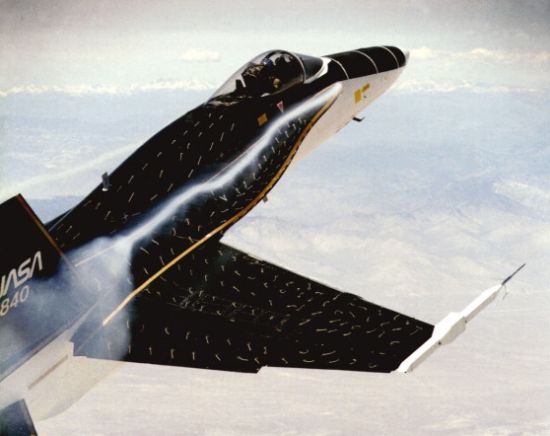
Types of Vortex BreakdownTwo types of vortex breakdown have been identified in experiments: spiral type and bubble type. These are named after their physical characteristics. On delta wings both types have been shown to exist at the same time in water tunnels, i.e. at low Reynolds numbers. The bubble type has not been found at high Reynolds number and thus it has been proposed that this mode may only be the result of an instability in the spiral mode. Another proposal has been that bubble type vortex breakdown is just a spiral vortex breakdown staying at the same coordinates lengthwise all the time. In delta wing flow the spiral type is most dominant. In experimental studies it has been noted that transition between both types is very sensitive to changes in both Reynolds number and angle of attack. The transition can be both back and forward between the two types with small changes in Reynolds number and angle of attack .Payne et al observed that the the two modes transform from one tothe other in an apparently random way. The bubble type of vortex breakdown seemed to prefer a more upstream location relative to the spiral mode of vortex breakdown. Payne et al also observed a behaviour consistent with what Lowson reported in 1964 that the breakdown took the form of a bubble when moving upstream and a spiral when moving downstream. The transformation from one type to another was not observed to be instantaneous but involved a continuous sequence of intermediate forms that were hard to classify as either spiral or bubble. Figure 2.4: Bubble-type breakdown topology Figure 2.5: Spiral-type breakdown topology The vortex breakdown displayed in Figure 2.7 is of the spiral type.2.2.3 Effect of Angle of Attack Angle of attack is the key feature that influences the vortex breakdown position for a delta wing. Therefore it is most important to understand how the change in angle of attack influences the vortex breakdown position. When the angle of attack, α, of the delta wing is increased the leading edge vortices strengthens until α reaches a certain value and the vortex starts to breakdown. Asα increases beyond that certain value the vortex breakdown starts to moveup stream, crossing the trailing edge and finally reaches the apex. Vortex break-down is associated with α greater than 10◦. Wentz and Kohlman [32] also 1M. V. Lowson ”Some Experiments with Vortex Breakdown”, Journal of Royal Aeronau-tical Society Vol. 68 May 1964
Figure 2.6: The two different types of vortex breakdown, top spiral, bottom bubble, made to coexist. [18]Figure 2.7: Picture of NASA’s F-18 HARV experiencing vortex breakdown
defined initial breakdown as a critical value of α when the vortex breakdown crosses the trailing edge. The fact that the vortex breakdown position is moving upstream towards the apex from the trailing edge results in a reduction of lift and rapidly changing pitching moment with respect to α . However, due to the vortices, the delta wings does not experience the dramatic loss of lift as anordinary wing does at stall. Instead the CL α-curve slope shows a much slower rate of lift loss for the delta wing. Effect of Leading Edge Sweep Angle There is a consensus in previous work that delta wing characteristics are to a large extent dependent on the sweep angle of the leading edge. The vortex breakdown position is affected by the leading edge sweep angle. When the sweep angle is decreased the vortex breakdown position is moved towards the apex of the delta wing. Also, an increase in adverse pressure gradient will move the breakdown position towards the apex. Erickson states that for the wings he tested there was a linear relation between wing sweep angle and the vortex core angle. The vortex core angle is the angle between the wing and the vortex core. Furthermore, Erickson draws the conclusion that the vortex core angle for a given leading edge sweep is relatively insensitive to changes in angle of attack. The difference between vortex core and leading edge sweep angle diminishes as the wing sweep is increased . In [11] Payne et al comes to the conclusion that at a given angle of attack, as the sweep angle is increased the location of the vortex breakdown moves aft.2.2.5 Effect of Leading Edge Shape Since the vortical flow is highly dependent on the separation at the leading edge of the delta wings it is readily apparent that the shape of the leading edge will have an influence on the flow characteristics. The shape of the leading edge is significantly influencing the position of the vortex breakdown location, as discussed by Kegelman and Roos Sharp edged, single bevel wings tended to force breakdown earlier at low angles of attack compared to blunt edgedwings. At higher angles of attack the difference was much lower however, and probably within the bounds of experimental error. The shape of the different leading edges can be found in the figures and.The t/c ratio for wings tested by Ng et al in do not seem to have any effect more than a increasing roundness to the leading edges that changes the vortex breakdown position as stated above. Effect of Freestream Disturbances The vortical flow is of a sensitive nature and easily disturbed both by upstreamand downstream disturbances. Given the limitations of ground-based test facilities this is a significant issue in enabling tunnel results to be extrapolated to free-flight. Upstream disturbances are minimised in any wind or water tunnel, however some degree of flow turbulence is unavoidable and hence must be considered. Downstream disturbances will be introduced from objects such as stings. As such, the effect of these disturbances must be studied.
Figure 2.8: Effect of very sharp leading edges Figure 2.9: Effect of sharp leading edge wind ward Figure 2.10: Effect of blunt leading edges According to Lee and Ho in there has been little research conducted on the effect on vortices of free stream disturbances. Lee et al state that Lambourneet al found that a spoiler placed in front of or at the apex did not interfere with the vortex. However Lee et al claims that the vortex breakdown became very unstable when the freestream turbulence was increased from 0.5% to 1.5%. However the general consensus is that disturbances upstream will effect the vortex breakdown to a significant extent. Mabey comes to the conclusion that upstream disturbances strongly influences the the amplitude of the limit cycle oscillation, also known as wing rock. Downstream disturbances on the other hand is not subjected to a lot of research. But there is shown in, for example, that the sting totally changes the vortex breakdown position. This is a significant problem because of the presence of a sting and support mechanism downstream in most water and wind tunnel studies. The effect of the sting and rig can be clearly seen in Figure 2.11
Page 26
Figure 2.11: Interference of sting and rig to the flow around a model Effect of Reynolds Number One of the most important issues is to what if any extent these phenomenon are dependent on Reynolds number. If they are dependent there is little use of testing them in the water tunnel since the Reynolds number is so low. In previous sections of this report the Reynolds number dependency has been discussed for each phenomenon, this section intends to sum up these issues and provide asummary of the current consensus in the area. On conventional wings the lift and the drag are dependent of the boundary layer over the wing and therefore strongly dependent on Reynolds number. Delta wing flow are however associated with vortex flow over a certain value of α. At angles of attack greater than 10◦ vortex breakdown will typical occur at some distance downstream of the apex ]. This is due to the fact that the flow will separate at the leading edge from which a primary vortex sheet originates. According to Erickson in the strength of the vortex sheet is independent of Reynolds number. Also Erickson in stated that the variation with respect to Reynolds number are smaller then the variation between different test facilities. It is important to realise that secondary flow separation are strongly dependent of Reynolds number. Even if vortex breakdown is considered to be independent of Reynolds number Roos and Kegelman in [26] detected a small dependence in CLmaxof Reynolds number. CLmax seems to slightly decrease with increasing Reynolds number But even Roos and Kegelman note that no significant variation was detected in their experiments. The fundamental conclusion that can be drawn from this literature study is that vortex breakdown can be treated as Reynolds number independent for the purposes of this study. This provides justification for the present experimental
study, given the prevalence of vortex breakdown in wing rock. Of course, many other factors are also significant and these may have significant impact. Some of these aspects are discussed in direct relation to wing rock in the next section, although at this juncture it is sufficient to observe that the recent overview of wing rock research by Katz found generally good correlation between wind and water tunnel studies.2.3 Wing Rock As discussed previously, supermaneuverability to a large extent incorporates high α maneuvers and at the same time motion in some or all of the six degrees of freedom. During such high α maneuvers the vortex flow will to a large extent determine the flight characteristics of the aircraft. As the angle of attack increases the more important factor is the vortex flow and the more sensitive it is to disturbances that might occur when the aircraft, for example, makes a roll. Dynamic rolling will in conjunction with high α result in changes in the vortex core position and the vortex core breakdown position and might induce a limit cycle roll motion known as wing rock. Modern fighters may be limited in their combat maneuvering by the onset of wing rock. Wing rock is the moderate to high angle of attack dynamic motion that is primarily a limit cycle oscillation in roll with, in some cases, an oscillation in yaw The build up of wing rock will continue until a stable limit cycle is established A typical wing rockbuild up is shown in figure 2.12. Note how the rocking slowly builds up to a maximum value. The motion are also called a Limited Cycle Oscillation.Figure 2.12: Wing rock build up α and ΛLE The wing rock motion seen over time are shown in figure 2.12 In the transonic Mach region, wing rock can occur at moderate angles of attack as a result of shockwave and boundary layer interactions on the wing, but it can also occur at speeds lower than corner speed if the aircraft is near to stall . It is wing rock at these lower speeds that is of interest in this study. Wing rock is in general the loss of stability in the lateral/directional mode which can be caused by several different aerodynamic phenomena, as will be discussed in the next section. For many aircraft wing rock is caused by the influence of the assymetrical leading edge vortices have on the surfaces
Figure 2.13: Wing rock motion the asymmetrical wing leading edge vortices have on the surfaces
Example of asymmetric vortex breakdown are shown i figure 2.14 Mabey states that there are two alternative sequences that are expected to occur as the angle of attack increases. The first is typical for delta wings with low to moderate sweep. The model motion in roll may be described by random buffeting which increases steadily and then decreases. This motion is similar to the variation of the buffet excitation on an airfoil with separated flow. The alternative sequence is that the model motion may be excited by initially random buffeting but at a higher angle of attack it may develop into a large amplitude limit cycle oscillation in roll. At even higher angles of attack the motion reverts to low amplitude buffeting. The most common way to present the wing rock boundaries for different delta wing is in a graph displaying ΦMAX versus α. Katz presents a graph over the wing rock domains for different delta wings in see figure 2.15. This graph can also be found in the work by Ng et al As seen in the figures 2.3 and 2.15 it seems unlikely that the wing rock mechanism would be solely dependent on the vortex breakdown phenomenon since the curves do not give the same result for onset angle of attack for the vortex breakdown over the wing and roll angle at slightly lower angle of attack. If a hysteresis plot is produces for the wing rock motion it typically looks like figure 2.16 from. This hysteresis curve is originating from wind tunnel tests. One relevant observation reported by Katz is that water tunnel tests of the wing rock hysteresis behaved qualitatively in the same way, but in the opposite direction.This phenomenon have also been found by Nelson Figure 2.14: Example of asymmetric vortex breakdown over a delta wing
Page 30
Figure 2.15: Wing rock domains plotted as φ versus α for different ΛLE Wing Rock Mechanism, There is a wide consensus that wing rock is mainly caused by asymmetric vortex breakdown on the upper side of the delta wing. The initial roll and angle of attack of a delta wing are the primary determinants if wing rock occurs. In general it is concluded that wing rock is mainly caused by vortex breakdown. By contrast Ericson suggested that asymmetric vortex shedding was the key mechanism of wing rock. In Arena and Nelson comes to the conclusion that the vortex core lift off is one of the primary mechanisms responsible for driving the wing rock motion. The vortex core lift off, in conjunction with time lag, produces results which can be shown in hysteresis loops. These hysteresis loops give a picture of the mechanism behind wing rock. Ericsson draws the conclusion that the vortex breakdown have a destabilising effect on wingrock. Furthermore Katz [16] states that vortex strength must have an effect, maybe dominant, in driving the wing rock and he furthermore draws conclusions from experiments made by Katz and Levin [20] that the asymmetric vortex breakdown has a damping effect on the wing rock. In Ericsson states that the mechanism driving the wing rock motion is the time lag that the statically stabilising vortex induced load are subjected to. Ericsson also discuss that a centerbody on the models can induce an upwash along the leading edge that generates a negative camber that in turn promotes vortex breakdown. This generates vortex damping of the wing rock to occur at lower angels of attack.A schematic position of the vortex core during wing rock is shown in figure2.17. When looking forward from behind the wing one can clearly see the asymmetric vortex core positions [16]. In this case the core on the upward rolling
semispan is closer to the wing and therefore increasing suction on this side which in turn is expected to increase the lift while the lift decreases on the opposite side This difference in force will result in the rolling moment driving the wing in the direction of the motion. Katz also states that the steady state restoring moment on delta wings increase with roll angle. This effect is then expected to resist the motion, during the dynamic case as well, towards larger roll angles and will eventually stop and reverse the motion Mabey found it useful to discuss wing rock in terms of the Frequency parameter, n, defined as:n =√fc/U and the Inertia parameter defined as√ρSbc2/I The inertia parameter is also known as the apparent mass parameter as it represents the displaced mass due to the presence of the surrounding fluid. In figure 2.18 [21] one can see the variation of frequency parameter for a range of the inertial parameter. These two parameters can be derived from the quasi-steady theory used by Mabey. Mabey uses these parameters to refer results from wind and water tunnel tests to real aircraft. Figure 2.18: Graph over the inertia parameter Mabey found that the scale effects to the models he used were relatively small on the wing rock phenomenon. This was expected he concludes since the wing rock phenomenon involves displacement of large scale vortical flow.
2.3.2 Roll DampingA loss of roll damping is indicative of the onset of wing rock. The damping in the system tends to reduce the amplitude and frequency of the wing rock The longer span, or higher aspect ratio, the higher the roll damping. If the roll damping is high then the tendency for wing rock is low. Roll damping is also increased with increasing moments of inertia around the roll axis. Mabey comes to the conclusion that fences on the wing itself, fins or leading edge fences primarily increase the aerodynamic damping. Mabey also states that these passive devices change the frequency parameter of the motion, see section 2.3.1, only slightly. Mabey compares the influence of inertia to wing rock. The influence are investigated by using similar shaped pods on the fins but with varying mass density. The materials Mabey used are brass, aluminum and balsa. Mabey states that the wing rock amplitude are not so dependent on the speed of the freestream. Furthermore he draws the conclusion that bearing friction and not aerodynamic forces are the most influencing factors to the amplitude of wing rock in the wind tunnel. Mabey also noted that the amplitude increases some what as inertia decreases and that as inertia increases it becomes more difficult to initiate the motion. Mabey’s conclusion is that ”friction in the rig and inertia of the model must be minimised at the same time the free stream velocity has to be maximised to get reliable results.”One example that the friction is a very important issue to address presented by Morriset . One can clearly see in figure 2.19 that the friction plays a major part in the results of wing rock testing. Figure 2.19: Effect of friction on wing rock Ericsson also discusses roll induced damping. By this Ericsson refers to the fact that the down stroking wing half will experience an increased vortex induced lift while the up striking half will experience a decreased vortex induced lift. Ericsson states that this roll induced damping is needed to establish a limit cycle oscillation before vortex breakdown occurs on the wing and effectively stops any further amplitude growth.
Mabey refers to a work by Ross, Foster and Turvey, RAE TR 78-032 that states that onset of wing rock is due to lack of damping in a Dutch roll mode, itself due mainly to loss in roll damping derivative at high angles of attack.The importance of wing rock studies can be questioned by the fact that an aircraft has six degrees of freedom and most studies only take one degree of freedom into account. In flight wing rock is often combined with a motion in yaw resulting in a dutch roll oscillation. However, according to Mabey in recent studies have revealed that the wing rock motion predominates for the F-15 Eagle, RF-4C Phantom II and T-38A Talon. Assuming that the minor secondary motions are results of, and not drivers of the wing rock, then a 1DOF approach should capture the necessary trends.2.3.3 The Importance of Wing Rock On an aircraft wing rock seldom reaches the high values of amplitude that is generally experienced in wind and water tunnel experiments. However the wing rock can be a major factor in for example air to air combat as it makes it drastically harder to aim guns or even for the pilot to concentrate on the fight. Another problem is that the pilot might not recognize the wing rock and think that something has gone wrong and abort the mission. Wing rock is hard to predict in flight testing and can occur at one altitude but not another. The phenomenon is so dependent upon detail aspects of the configurationthat those aircraft that have had problems due to wing rock have experienced different symptoms. The American F-18 Hornet, manufactured by McDonnell Douglas, suffers from control and fatigue problem associated to wing rock. Another American aircraft, the F-15 Eagle also manufactured by McDonnell Douglas, can experience quite significant directional control problems due towing rock. The Swedish SAAB 39 Gripen belongs to the newest generation of fighters with all digital controls and the wing rock problem is minor and only experienced when going out of superstall. Wing rock can restrict the operational envelope of the aircraft. This means that wing rock must be avoided, hence limiting the flight envelope. Another remark is that the part of the envelope where wing rock is experienced in the Gripen is seldom used and of little operational use for most fighters. They are not flying at such high angle of attack that wing rock is a major problem.22 This information was supplied in a personal communication with Col.Lt Bjorn Johansson,FMV, Linkoping, Sweden.
0.6
Sourcehttp://www.flumes.ikp.liu.se/aero/report/wingrock_rpt_draft.pdf
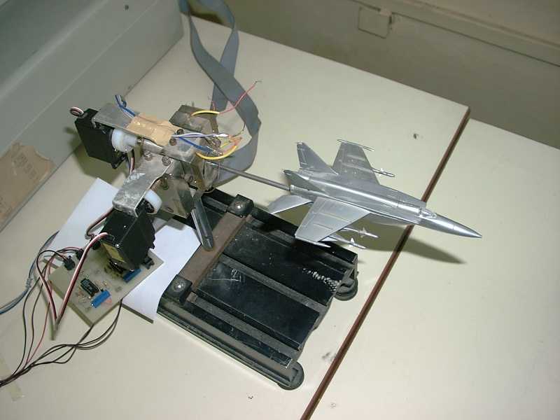
Wing Rock Demonstrator
A 2 Axis motion platform that is driven by a PC to position an aircraft model in pitch & roll. Aircraft dynamics runs off the PC and is used to position the model for visual effect. The aircraft position is sensed using potentiometers and fed back to the PC. The feed back can be used for implementing control strategies. A 486 PC along with PCL208 DA/AD card is used. The motion platform is driven by low cost servos used by hobbyists. Wing rock is a well studied non-linear flight dynamic, limit cycle phenomena. Dr. Hemendra Arya is the driving force in this activity.
http://www.aero.iitb.ac.in/~sudhakar/Laboratory/lab-dev.html
MiG-23 MLD, as mentioned earlier the research paper from Vigyan Inc. mentions that it’s suggestion is a spoiler-like surface that extends over the wing’s leading-edge and which deploys vertically. The same is the description of slats, with the exception that it does not deploy vertically unlike the paper’s requirement.
Note that the paper has made a second suggestion of apex-flaps as the solution to the same problem, which is fulfilled by slats. Thus, regardless of the absence of apex-fence (in lieu of apex-flaps instead), the same aerodynamic problem stands fully solved on the Tejas.
Now, as the proposed LEVCONs on the naval Tejas will be vertically deployable, they will in fact be the “faithful” implementation of apex spoiler-like surfaces (apex fence) as mentioned in the paper.
Loofahboy, in my view, as indicated in the article, Taiwan’s proposed fighter is likely to be a conventional fighter with indigenous RAM coating only.
Abhimanyu
I am not an aerodynamist and i am still learning, i think the LEVCONs seem to be the closest thing to a apex wing fence i can imagine if i try to agree with you, however the LEVCON is not called Apex wing fence, but perhaps later i can confirm you if they are or are not but they seem to be the same.
However i disagree in one aspect with you, if the LEVCON and leading edge notch increase lift according to the LCA`s needs, i do not see their advantage beyond lift and stability at high AoA.
The canard it`s in that regard a bit more complex since the aircraft has two centers of lift flanking the center of gravity, thing that does not happen even with the LEVCON.
Besides LEVCONs are not part of the LCAs that have been built up to now.
However the LEVCON seems to be a very ingeneous way of improving AoA behavior at low speeds by increasing lift and reattaching the vortex.
In the F-16XL its wing fences have the following feature:
the General Dynamics F-16XL, incorporate the use of vertical fins or fences located outboard on the wings (generally placed at the crank location). Grafton found that the effect of fences located just inboard of the wing crank on a predecessor of the F-16XL (Fig. 5a) reduced the lift and created a slight improvement in the pitch-up at high angles of attack as shown in Fig. 5b. In a later test of a similar model, Grafton and Nguyen found that the slope of the pitching moment curve after the pitch-up increased with the addition of the wing fences at moderate angles of attack (decreasing longitudina lstability), and improved the longitudinal stability slightly at high angles of attack. Lockwood tested a modified SCAT-15F model and found that vertical fins (whether located at the crank or inboard of the crank) reduced the longitudinal stability as well as the lift. This result is contradictory to Grafton and Nguyen’s findings Both researchers agreed, though, that the effects were likely due to the loss of vortex influence on the outboard wing section and vortex breakdown due to the presence of the fences. Another effect of the fences or fins in these tests was to cause the inboard vortices to break down symmetricallyin side-slip, thus improving lateral stability
http://www.aoe.vt.edu/~mason/Mason_f/ABMSThes.pdf
If you see more or less are the effects for the wing apex fences see:
Conversely, at high angles of attack when the basic delta wing apex is highly loaded, the fences reduce the apex lift resulting in pitch down acceleration for a return to normal flight attitude
http://pdf.aiaa.org/preview/1986/PV1986_1838.pdf
As tags are open to distill one’s own grasp on a particular thread, I think they should remain as they are. Just add your own two if you disagree. As long as they remain within the standard ToS, there’s no need to change anything about them.
And how do they interfere with searches? Of course you only click those tags that make sense in your judgment, so all other tags can’t possibly get in your way. For everything else, there’s the standard search.
I think all the tags that are tossed to insult members anonymously are crap, for example you get so irrelevant and frankly foolish ones just to claim anonymously foolish claims which do not help the threads in any way.
For example a useful tag is for example in a MiG-21 thread is J-7, same will be for example gulf war in a thread of the F-15, but the rest such as: irony, LCA the best, in five seconds or star49 are simply useless.
Why do i need to see tags that are frankly anonymous insults directed to a fellow member? that does not help in any way just shows how foolish are some members and just feed trolls to use tags as another way of annoy people
This is probably the closest thing to Apex wing fences i can imaging however are called LEVCon and are basicly wing root apex slats
LEVCON
LEVCON ( Leading Edge Vortex CONtroller ) is a deflectable aerodynamic device in wing apex region LEVCON surface is deflected +20 (down) to 30 (up) from its neutral position.Downward deflection of LEVCON is used for reducing aproach speed for carrier landing 
http://www.lca-tejas.org/naval%20tejas.html
Let us say these are not operational niether part of the LCA currently built since these are for carrier operated LCAs which have not been built yet and therefore are simple aerodynamic concepts
However this is aerodynamically supported by the following
Modified F-16XL predecessor model Much like the leading edge notch, the shape and incidence of the leading edge can affect the vortex lift and the following features, so as we can see the LCA is basicly very similar to the F-16XL since The leading edge can also be shaped and deflected such that the leading edge vortex is maintained on this surface. Applying this concept to a leading edge device results in the so-called vortex flap. Generally used for transonic maneuverability, deflecting the leading edge allows for the development of vortex lift while recovering some of the leading edge-suction to reduce drag.
The LEVCON works as a leading edge notch slat
see Grafton also found major effects resulting from a leading edge notch on the same model. Here, the leading edge notch weakened the leading edge vortex, resulting in a reduction of the severity of the pitch-up.
you are very right mig-23 mld!!
the lca doesnt have canards, its well and truly !@#$’ed.
the lca doesnt have wing fences, its well and truly !@#$ed.
** lca is made by thirdworld country.
Reference: MiG-23 MLD. (who cannot be & is not wrong)
Since ADA says the same i said based upon what i read on NASA papers it shows how wrong and proud you are, you love being blinded by your own pride see
The tailless compound delta planform helps in keeping LCA small and light. It also means fewer control surfaces, wider choice of external stores and better close combat, high-speed and high-alpha characteristics.
LCA has been designed to be unstable. Relaxed static stability gives improved aerodynamic efficiency and enhanced agility and manoeuvrability.
I disagree, as the abstract is not ambivalent. Leading edge is the portion shown in red colour in the latest diagram posted by you, and where the Tejas 3 leading edge slats are located.
What is shown by you may be ‘fences’, but they are not descriptive of the abstract i.e. “hinged on the leading edge”, unlike slats. As per this article, Tejas’ slats are located on the leading edge, and are independently actuated i.e deflectable or hinged. The article describes their function to increase pitch-moment at high AoA — which is exactly the same described in the abstract.Besides, here it must be mentioned that the term ‘spoiler’ is a generic term used for any device on the wing that kills lift and/or brakes. The abstract posted by you earlier also terms slats as spoiler-like surfaces.
http://www.sarodonline.org/Dr._S.R.Mohan-abstract.pdf
This document proves the LCA has not Apex wing fences as you claimed
A three panelled wing with outboard anhedral, single pitch control surface and no leading edge device evolved into a two panelled wing with split elevons, no anhedral and a three piece leading edge slats on each wing
This further proves it has not Apex wing fences
LCA Configuration
Optimum Aerodynamic configuration evolved from extensive wind tunnel tests and Computational Fluid dynamic analyses.
Tailless compound delta configuration with size and weight advantage and better close combat, high speed and high angle-of-attack characteristics.
Relaxed Longitudinal stability with enhanced agility, maneuverability and performance
Optimized wing camber & twist, careful wing-body blending and area ruled fuselage for minimum wave drag and good high speed handling.
Wing-shielded bifurcated Y-duct air-intake with optimized diverter provides buzz free low distortion engine flow ensuring operability in entire envelope.
Leading edge slats scheduled for high angle-of-attack maneuvers and combat
See is ADA who claims that
http://www.ada.gov.in/adaweb/Activities/Designanalysis/AeroDynamics/LCA_Configuration/lca_configuration.html

Wing fences on a F-16XL

The size of the trailing edge notch of an arrow wing can dramatically affect the pitch-up behavior of highly swept wings. It was shown by Grafton that the addition of a trailing edge extension on a modified arrow wing planform (Fig. 5a) reduced pitch-up(done as part of the F-16XL planform development program). Although this modificationdid not change the angle of attack for pitch-up, it did reduce the severity of the pitch-up, as shown in Fig. 5b. Grafton also found major effects resulting from a leading edge notch on the same model. Here, the leading edge notch weakened the leading edge vortex, resulting in a reduction of the severity of the pitch-up. This result demonstrates the possible sensitivity of pitch-up and lift characteristics to small planform changes brought about if these small changes produce a fundamental change in the leading edge vortex.
deflected (to postpone the formation of the leading edge vortex) the pitch-up was a result of basic flow separation on the outboard wing section and not vortex breakdown. Some of the configurations developed such as the SCAT-15F, the AST-100 and AST-200 series, and the General Dynamics F-16XL, incorporate the use of vertical fins or fences located outboard on the wings (generally placed at the crank location). Grafton found that the effect of fences located just inboard of the wing crank on a predecessor of the F-16XL (Fig. 5a) reduced the lift and created a slight improvement in the pitch-up at high angles of attack as shown in Fig. 5b. In a later test of a similar model, Grafton and Nguyen found that the slope of the pitching moment curve after the pitch-up increased with the addition of the wing fences at moderate angles of attack (decreasing longitudina lstability), and improved the longitudinal stability slightly at high angles of attack. Lockwood tested a modified SCAT-15F model and found that vertical fins (whether located at the crank or inboard of the crank) reduced the longitudinal stability as well as the lift. This result is contradictory to Grafton and Nguyen’s findings. Both researchers agreed, though, that the effects were likely due to the loss of vortex influence on the outboard wing section and vortex breakdown due to the presence of the fences. Another effect of the fences or fins in these tests was to cause the inboard vortices to break down symmetricallyin side-slip, thus improving lateral stability. Further Considerations The formation of the leading edge vortex has been shown to be affected by Reynolds number. Furlong and McHugh addressed the effect of Reynolds number in their summary of the aerodynamic characteristics of swept wings. They showed that the effect of Reynolds number on the leading edge flow separation was more prominent for wings with airfoil sections having rounded leading edges than sharp leading edges (Fig. 7). The“inflection” lift coefficient used in Fig. 7 refers to the lift coefficient at which there is an increase in lift coefficient due to the formation of a leading edge vortex.The insensitivity of vortex flow to Reynolds number effects has been shown by a variety of researchers by analysis of force data taken from tests of HSCT planforms. The variation of Reynolds number for these tests were on the order of about one magnitude. However, Re and Couch found that Reynolds number variations during the testing of a SCAT-15F model did affect the measured forces. The size of the trailing edge notch of an arrow wing can dramatically affect the pitch-up behavior of highly swept wings. It was shown by Grafton that the addition of atrailing edge extension on a modified arrow wing planform (Fig. 5a) reduced pitch-up (done as part of the F-16XL planform development program). Although this modificationdid not change the angle of attack for pitch-up, it did reduce the severity of the pitch-up, asshown in Fig. 5b. Grafton also found major effects resulting from a leading edge notch on the same model. Here, the leading edge notch weakened the leading edge vortex,resulting in a reduction of the severity of the pitch-up. This result demonstrates the possible sensitivity of pitch-up and lift characteristics to small planform changes brought about ifthese small changes produce a fundamental change in the leading edge vortex.
Page 15
Page 7Nose-upCM-0.05CL0.250.50ABCDABCDFigure 4. – Variation of pitching moment for a 75 sweep arrow wing with varying trailing edge notches (ref. 37).Wing FenceTrailing-EdgeExtensionLeading-EdgeNotch0102030400.00.40.81.21.6CLα (deg)BaselineApex ModApex+TE ModApex+TE+Fences0.000.050.10CM(a) Model diagram with trailing edge(b) Lift and pitching moment data for several extension, leading edge notch, and configurations (ref. 38)wing fence.Figure 5. – Modified F-16XL predecessor model Much like the leading edge notch, the shape and incidence of the leading edge can affect the vortex lift. Increasing the leading edge radius has the effect of improving thelongitudinal characteristics by retarding the formation of the leading edge vortex. This also reduces the vortex lift, as shown in Fig. 6. The local angle of attack of the leading edge seems to have the greatest effect on the aerodynamic characteristics with respect to the pitch-up. To minimize the formation of the vortex, it is desirable to deflect the leading edge
——————————————————————————–
Page 16
Page 8 such that the leading edge incidence relative to the local flow angle of attack at each spanwise station is zero. Then, at angles of attack above this condition, the vortex will be formed uniformly. The leading edge can also be shaped and deflected such that the leading edge vortex is maintained on this surface. Applying this concept to a leading edge device results in the so-called vortex flap. Generally used for transonic maneuverability, deflectingthe leading edge allows for the development of vortex lift while recovering some of the leading edge-suction to reduce drag. The vortex flap shape and wing camber must be optimized for minimum lift-induced-drag to be effective. The effects of leading and trailingedge flaps will be discussed in more detail in the following section.0.000.05CM5101520250.30.50.70.91.11.3L.E. RadiusCLα (deg)0.2% c0.5% c1.0%cFigure 6. – Effect of leading edge radius on lift and pitching moment on the SCAT-15F (ref. 16)Planform effects, such as the outboard wing sweep, were studied by Hom, Morris,and Hahne.40Hom, et al, theorized that the pitch-up was a result of flow separation on the outboard wing panel, a function of the spanwise flow, and vortex breakdown. Four models were tested with a 70 sweep inboard wing section and varying outboard wing sweeps ranging from 60 to -20. They found that the lower sweep outboard wing panels encountered less spanwise flow and thus, the flow remained attached on the outboard panels. As the outboard sweep angle was increased, the flow on the outboard wing section separated and became dominated by a leading edge vortex on this section. The angle of attack for pitch-up was found to be unaffected by the outboard wing sweep. However, helium bubble flow visualization techniques showed that the cause of the pitch-up varied for the cambered and uncambered wings. It was found that the pitch-up for the uncambered wings was due to vortex breakdown at the trailing edge. When leading and trailing edge flaps were
http://www.aoe.vt.edu/~mason/Mason_f/ABMSThes.pdf
I disagree, as the abstract is not ambivalent. Leading edge is the portion shown in red colour in the latest diagram posted by you, and where the Tejas 3 leading edge slats are located.
What is shown by you may be ‘fences’, but they are not descriptive of the abstract i.e. “hinged on the leading edge”, unlike slats. As per this article, Tejas’ slats are located on the leading edge, and are independently actuated i.e deflectable or hinged. The article describes their function to increase pitch-moment at high AoA — which is exactly the same described in the abstract.Besides, here it must be mentioned that the term ‘spoiler’ is a generic term used for any device on the wing that kills lift and/or brakes. The abstract posted by you earlier also terms slats as spoiler-like surfaces.
Abhimanyu
I do not agree with you for several reasons, in the article i posted previously says the F-16XL outboard fences do control vortices that enhance stability and pitch.
http://www.aoe.vt.edu/~mason/Mason_f/ABMSThes.pdfYou are saying that slats are these fences, it can not be slats are slats and fences are fences see
The F-106 had fences on its wings to improve vortices stall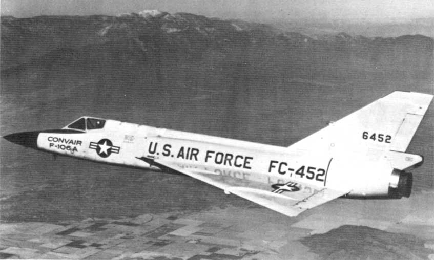
See slats are obvoiusly hinged
Its obvious you can not distinguish between slats and leading edge flaps

F-16 in a hard turn with wing leading-edge flaps deflected and vortices produced
by the sharp wing-body strakes illustrated by condensation
see the hinged parts in red color in the F-16XL model, the LCA has leading edge flaps but not apex fences as you claim
Extensive tests for SCAMP took place in Langley facilities, including the Unitary Plan Wind Tunnel, the 7- by 10-Foot High-Speed Tunnel, the 16-Foot Transonic Dynamics Tunnel, the Full-Scale Tunnel, the DMS, the Spin Tunnel, and a helicopter drop model. During these tests, a team led by researcher Joseph L. Johnson, Jr. identified low-speed stability and control issues that required modifying the wing apex with a rounded planform. Research on the SCAMP configuration by Langley researchers identified numerous advanced concepts for improved performance, including the application of vortex flaps on the highly swept leading edge for improved low-speed and transonic performance, automatic spin prevention concepts, and optimized wings for supersonic cruise. The final configuration became known as the F-16XL (later designated the F-16E), which displayed an excellent combination of reduced supersonic wave drag, utilization of vortex lift for transonic and low-speed maneuvers, low structural weight, and good transonic performance. The F-16XL flutter envelope was cleared in the 16-Foot Transonic Dynamics Tunnel by Charles L. Ruhlin without significant problems.
http://oea.larc.nasa.gov/PAIS/Partners/F_16.html
http://oea.larc.nasa.gov/PAIS/Partners/FA_18.html
F/A-18 with wing leading-edge flaps deflected and LEX vortices made visible by condensation


 Sign In
