MiG-23MLD
I am sure that the parameters were selected to make those statistics the most favorable to the F-14, but they support the general position that the F-14 is a better fighter. I am sure that the improved acceleration is due to the lower drag when the wings are fully swept, because the TF-30 engines are nothing to brag about beyond improved fuel consumption. The better climb and turning ability is due to a much lower effective wing loading. That tunnel between the engines makes a big difference. A jet like an F-105 or MiG-23 isn’t going to get much lift from the fuselage, but the F-14 pancake fuselage isn’t just bigger, its flatter, and acts much more like an airfoil. Wing area figures that just include the wings really don’t mean anything. High lift devices on the wings make a difference too.
All those figures are for an F-14A. The F-14D should be much better.
The F-14 in my opinion was an excellent aircraft a real beauty, is it better than the F-4 ?undoutedly it was and is, but comparing an old aircraft with aln older one well is not fair, the F-14 was not as good as the F-18 in agility and despite it always was protraited as a super agile fighter it had reduced G limits due to structural troubles.
Yeah on paper it was better than the F-4, but in practice the F-14 never was as good as the F-16 or F-18 in agility, it only could compete while the AIM-120 was not around and armed with AIM-7 and no AIM-154 its combat days were counted.
In fact the British said the F-14 armed with only AIM-7 were not better than the F-4 as interceptors
MiG-23MLDDucommun Incorporated Announces New Manufacturing Facility in Mexico.
Publication: Business Wire
Date: Tuesday, June 26 2007
You are viewing page 1
LOS ANGELES — Ducommun Incorporated (NYSE:DCO) today announced that its Ducommun AeroStructures (DAS) subsidiary has established a subsidiary in Mexico for the production of aircraft structural components and subassemblies for commercial aircraft.
DAS has established an office in coordination with The Offshore Group in Mexico, and has signed a long-term lease for a purpose built facility specifically designed to meet its unique production requirements. The facility is located in Guaymas, in the Mexican State of Sonora, approximately five hours south of San Diego on the eastern shore of the Gulf of California. DAS is developing the site to accommodate future expansion of the facility as required to meet the growing needs of the global marketplace and expects to initiate production during the fourth quarter of this year.
Joseph C. Berenato, chairman and chief executive officer of Ducommun, stated, “We are pleased to announce the establishment of Ducommun AeroStructures (Mexico) Ltd. The new production facility will allow DAS to increase its productivity and competitiveness which will enable DAS to seek new business in the highly competitive global aerostructures marketplace. This facility will complement our existing Thailand facility opened last year and allow us to evaluate new productivity initiatives across the Company.”
Ducommun AeroStructures manufactures large, complex structural components and assemblies in aluminum, specialty alloys such as titanium, metal bond and composites for a wide variety of military and commercial aerospace applications.
Founded in 1849, Ducommun Incorporated provides engineering and manufacturing services for the aerospace and defense industry.
The statements made in this press release include forward-looking statements that involve risks and uncertainties. The Company’s future financial results could differ materially from those anticipated due to the Company’s dependence on conditions in the airline industry, the level of new commercial aircraft orders, production rates for Boeing commercial aircraft, the C-17 and Apache helicopter rotor blade programs, the level of defense spending, competitive pricing pressures, manufacturing inefficiencies, start-up costs and possible overruns on new contracts, technology and product development risks and uncertainties, product performance, risks associated with acquisitions and dispositions of businesses by the Company, increasing consolidation of customers and suppliers in the aerospace industry, possible goodwill impairment, availability of raw materials and components from suppliers, and other factors beyond the Company’s control. See the Company’s Form 10-K for the year ended December 31, 2006 and Form 10-Q for the quarter ended March 31, 2007 for a more detailed discussion of these and other risk factors
sourcehttp://www.allbusiness.com/services/business-services/4528191-1.html
Aernnova launches aerospace cluster in Ann Arbor
Posted by Nathan Bomey/Ann Arbor Business Review September 20, 2007 13:41PM
Categories: Manufacturing, Top Stories
One key component of Spanish aerospace firm Grupo Aernnova’s decision to open a $10 million engineering operation in Pittsfield Township was the lack of competitors in the region.
But the company doesn’t expect it to stay that way.
Aernnova executives said that other aerospace firms may follow them to Ann Arbor.
The company, also called Aernnova Aerospace S.A., just announced plans to invest $10 million to open a facility at the Valley Ranch Business Park, near Ellsworth and Lohr roads.
The firm expects to hire 400 workers within four to five years and projects expansion to 600 over a 15-year period.
Luis Perez, Aernnova senior vice president, said the company was looking for a location with broad availability of talent and an excellent engineering school nearby.
The company, which also considered some 15 other states, eventually narrowed its decision to Ann Arbor, Atlanta and Austin, Texas.
Perez said Aernnova is watched closely by similar companies – particularly in Spain. He said Aernnova is pleased to be one of the first major aerospace companies to locate here, but he suggested that might not last.
“I’m not quite sure whether we are going to be alone for a long time or not,” Perez said.
Aernnova received a tax credit worth $18.5 million over 15 years from the state and is expected to receive a 12-year, $400,000 tax abatement from the township.
The company is negotiating with the McMullen Company for space in the Ponds South Office Center at 3891 Ranchero Dr., said Ted McMullen.
The engineering operation will create an estimated 657 indirect jobs, according to an analysis conducted by the Michigan Economic Development Corp.
The company, officially called Aernnova Engineering U.S. Inc., hope to start the operation by mid-November and expand to 20 to 25 workers by the end of the year.
Aernnova also considered the city of Ann Arbor, Ann Arbor Township, the city of Saline and possibly others (Business Review, Aug. 9-16). The company worked with Ann Arbor SPARK throughout its search process, which started in February.
The visibility of the local aerospace industry is sure to increase with Aernnova’s decision to start the engineering operation here – its first engineering facility outside of Spain. The global company has 3,050 employees and its customers include companies such as Boeing, Airbus, Embraer, Sikorsky and Bombardier.
Michael Finney, CEO of Ann Arbor SPARK, said Aernnova’s decision to come to Ann Arbor gives the community a “significant international business attraction component” that will boost SPARK’s efforts to market the community globally.
“We think that Aernnova coming here and having a favorable experience with our state and our community will allow them to provide a very favorable reference for Ann Arbor” with other contacts in industry and Europe, Finney said.
J. Gregory Sweeney, principal of Port Townsend, Wash-based JGS International Advisors, helped Aernnova search for a location in America.
Sweeney said the company considered places like Phoenix, which has a booming aerospace industry, but opted against jumping into the fray.
“We quickly realized you’re the last guy in, in a tight, competitive market,” Sweeney said. “We knew we had to dig a little deeper, find a place where there are resources you can tap.”
The U.S. represents about 60 percent of the global aerospace market, Perez said. That reality, in addition to a favorable Euro-to-dollar currency exchange rate, influenced the decision to open a U.S. engineering operation.
The company hopes to target additional business with American firms such as Boeing.
As the domestic auto industry restructures, the state’s political and economic leaders have focused on retooling the extensive regional network of engineering talent for different industries.
Aernnova is perhaps the first major example of a company in a different sector of the economy that located here after identifying the engineering base in southeast Michigan as a source of future employees.
“The region seems to have very good skilled engineers available similar to what we will be looking for,” Perez said.
Juan Carlos Ortiz, managing director of Aernnova Engineering U.S., said the company uses a standard software suite called CATIA (Computer Aided Three-Dimensional Interactive Application) that is used to design aerospace equipment. The program also is used by automotive engineers.
Sweeney said engineers from Chrysler, Ford and Toyota use the software and that General Motors is considering using it.
Aernnova’s Pittsfield Township operation will focus on design and optimization of composite and metal aerostructures.
Ortiz said Aernnova’s first practical step toward establishing its operation in Pittsfield is setting up its information technology infrastructure, an extensive system that will eventually include dedicated transfer data lines to connect directly with its headquarters in Spain and its customers.
The township operation will focus strictly on engineering, although the company also has manufacturing and product services capability elsewhere. In early September, in fact, the company announced plans to invest $134 million over several years to establish facilities in Mexico that will produce parts for the plane and helicopter manufacturing industry.
The local aerospace industry includes companies like General Dynamics’ 450-person Michigan Research & Development Center in Ypsilanti Township and Liebherr Aerospace in Saline.
Aernnova officials cited the University of Michigan’s mechanical engineering and aerospace engineering departments as important factors in their decision to locate a facility in the Ann Arbor area.
Sweeney said reasonable proximity of an “excellent engineering university was critical very early.”
The other two major cities the company considered, Atlanta and Austin, have well-regarded engineering schools of their own, Georgia Tech University and the University of Texas at Austin.
U-M has more than 180 graduate students in aerospace engineering. The university also produced 16 doctoral graduates in aerospace engineering in 2006.
Elizabeth Parkinson, director of marketing and public relations for SPARK, said the need for talented workers and the desire to be close to U-M and Eastern Michigan University are common themes among companies interested in this area.
“We can’t underemphasize the role the universities have,” she said. “Probably 80 percent of our deals emphasize our institutions of higher learning.”
Finney credited the university for playing a major role in convincing Aernnova to come here. He said several U-M officials wrote or spoke to Aernnova executives about Ann Arbor, including President Mary Sue Coleman, Vice President for Research Stephen Forrest, Vice President for Government Relations Cynthia Wilbanks and Daryl Weinert, senior director of corporate and government relations in the College of Engineering.
“The role that major universities play in this state in economic development is becoming very important and the fact that U-M is embracing this role is making our job that much easier,” Finney said.
Aernnova is formerly the aeronautical division of Grupo Gamesa Corporacion Tecnologica. The company dates back to 1986, when it was called Fibertecnic. Gamesa Aeronautic was formed in 1993.
Aernnova – a private firm owned by Synergy Industry and Technology S.A. – spun out of Gamesa in April 2006. It is not to be confused with Aeronova S.L., which is a different Spanish aerospace company.
Aernnova has been expanding quickly. It had 2,640 employees in 2005 and 2,898 in 2006. Of the 258 people added that year, 140 were in engineering, according to the company’s 2006 annual report.
http://blog.mlive.com/ann_arbor_business_review/2007/09/aernnova_launches_aerospace_cl.html
a few good articles
http://www.bajaaerospace.org/Articles-Reports/Baja_California-Aerospace_Industry_August_2005.pdf
Honeywell division builds aerospace lab
By Diane Lindquist
UNION-TRIBUNE STAFF WRITER
May 3, 2006
Honeywell’s Aerospace division has broken ground in Mexicali on a $40 million systems integration lab where Mexican engineers will develop technologies for future commercial aircraft.
The lab represents a significant jump up the technological ladder for foreign investment in Baja California. Instead of manufacturing, like that performed by more than 1,000 maquiladora factories in the state, the Honeywell lab will develop and test a wide range of airplane flight systems.
AdvertisementBill Reavis, the spokesman for Honeywell Aerospace, said the facility was “designed to demonstrate a wide range of electric power subsystems and components and will have full-scale simulation of multiple aircraft systems.”
Honeywell’s clients include airplane manufacturers such as Boeing, Airbus, and Bombardier.
“The facility will be working with our Phoenix division headquarters,” Reavis said.
It is expected to come on line during the fourth quarter of this year in a 100,000-square-foot building and will start operations with about 100 engineers. An additional 200 engineers are expected to be hired in 2007.
Nearly all of those hired are expected to be Mexican engineers, Reavis said.
“We felt there was a good and dedicated work force there and a good supply of engineers,” he said.
For two decades, Honeywell Aerospace has had a maquiladora factory in Mexicali that produces an array of automation and control systems for aircraft. The factory had about 800 employees.
Honeywell’s Environmental & Combustion Control division operates a maquiladora in Tijuana.
Officials in Baja California and the maquiladora industry have been trying to attract industries like aviation and aerospace to the state as part of an effort to boost the region’s technological sector.
The decision to put Honeywell’s systems integration lab in Mexicali “makes sense given that Baja California has the largest concentration of aerospace manufacturing in Mexico,” said Kenn Morris, director of Crossborder Business Associates and lead author of a study for San Diego Dialogue that analyzed the competitiveness of the San Diego-Baja California region.
Not only are low-tech products being produced in Baja California for the aerospace/aviation sector, Morris said, but also components for such well-known weapon systems as TOW and Longbow missiles.
Besides Honeywell, other aerospace goods and equipment manufacturers in Baja California include Delphi Connection Systems, Gulfstream, C&D Aerodesign, Mexmil and Suntron. The state also is home to manufacturers with defense-related subsidiaries, suppliers or contract operations, including NASSCO, Cubic, Seacon Global, and MAGNETIKA.
“I think this will be one of many (aerospace operations) we’ll see in Baja California in the next few years,” Morris said
http://www.signonsandiego.com/news/mexico/20060503-9999-1b3mexicali.html
Mexico start building mc donnell douglas helicopters in Monterrey NL Mexico
http://www.economia.gob.mx/pics/p/p2000/unl_10_15.pdf


http://nl.gob.mx/pics/edito/54884/file.imageng3.jpg![http://nl.gob.mx/pics/edito/54884/file.imageng3.jpg"]http://nl.gob.mx/pics/edito/54884/file.imageng3.jpg](http://nl.gob.mx/pics/edito/54884/file.imageng3.jpg"]http://nl.gob.mx/pics/edito/54884/file.imageng3.jpg)
http://nl.gob.mx/pics/edito/54884/file.imagenc4.jpg![http://nl.gob.mx/pics/edito/54884/file.imagenc4.jpg"]http://nl.gob.mx/pics/edito/54884/file.imagenc4.jpg](http://nl.gob.mx/pics/edito/54884/file.imagenc4.jpg"]http://nl.gob.mx/pics/edito/54884/file.imagenc4.jpg)

source http://nl.gob.mx/?Article=54884&ArtOrder=ReadArt&P=leerarticulo&Page=1
MiG-23MLDHistorically, inlet complexity is a function of top speed for fighter aircraft. Higher Mach numbers require more sophisticated devices for compressing supersonic airflow to slow it down to subsonic levels before it reaches the face of the engine. (Jet engines are not designed to handle the shock waves associated with supersonic airflow.) These compression schemes involve the conversion of the kinetic energy of the supersonic airstream into total pressure on the compressor face of the engine. Speeds over Mach 2 generally require more elaborate compression schemes. The F-15 inlet, for example, contains a series of movable compression ramps and doors controlled by software and elaborate mechanical systems. The ramps move to adjust the external and internal shape of the inlet to provide the optimum airflow to the engine at various aircraft speeds and angles of attack. Doors and ducting allow excess airflow to bypass the inlet.
Inlet designs for fighter aircraft must also account for a layer of low-energy air that forms on the surface of the fuselage at subsonic and supersonic speeds. (These layers also form on the inlet compression surfaces.) This layer of slow moving, turbulent air, called a boundary layer, can create chaos when disturbed by the shock waves created by the inlet. The result can be unwanted airflow distortions at the engine face. If the shock wave/boundary layer interaction is severe enough, the engine will stall. The boundary layer thickens with increased speed and increased forebody distance, the length from the nose of the airplane to the inlet itself.
Designers of supersonic aircraft deal with this boundary layer phenomenon by redirecting the layer before it reaches the engine and placing the inlet away from the boundary layer in the freestream, where airflow is unaffected by the boundary layer phenomenon. On the F-16, a structure called a diverter provides a 3.3-inch gap between the fuselage and the upper lip of the inlet. The size of the gap equates to the thickness of the boundary layer at the maximum speed of the F-16. Other fighters remove boundary layer airflow with combinations of splitter plates and bleed systems. The latter redirect the unwanted airflow through small holes in the compression ramps to bleed ducts within the inlet. The DSI bump functions as a compression surface and creates a pressure distribution that prevents the majority of the boundary layer air from entering the inlet at speeds up to Mach 2. In essence, the DSI does away with complex and heavy mechanical systems
source http://www.codeonemagazine.com/archives/2000/articles/july_00/divertless_1.html

Diverterless Inlet
The F-35’s diverterless inlet lightens the overall weight of the aircraft. Tactical aircraft pose a formidable challenge for inlet designers. A fighter inlet must provide an engine with high-quality airflow over a wide range of speeds, altitudes, and maneuvering conditions while accommodating the full range of engine airflow from idle to maximum military or afterburning power. Historically, inlet complexity is a function of top speed for fighter aircraft. Higher Mach numbers require more sophisticated devices for compressing supersonic airflow to slow it down to subsonic levels before it reaches the face of the engine. Inlet designs for fighter aircraft must also account for the boundary layer of low-energy air that forms on the surface of the fuselage at subsonic and supersonic speeds. The on the Joint Strike Fighter performs miracles that only aeronautical engineers can fully appreciate. At high aircraft speeds through supersonic, the fuselage bumps at each inlet work with forward-swept inlet cowls to redirect unwanted boundary layer airflow away from the inlets, essentially doing the job of heavier, more complex, and more costly approaches used by current fighters. The diverterless inlet eliminates all moving parts.
http://www.globalsecurity.org/military/systems/aircraft/f-35-design.htm

MiG-23MLDNo, the Su-27 had original specs to be at least 10% better than the F-14A and F-15A. The Su-27 is larger than its American counterparts. This requirement to be at least 10% better than the Americans is in part, the reason it took so long to develope the Su-27. All three aircraft programs started in 1969. The F-14A became operational in March of 1974. The F-15A became operational Nov. 14, 1974, while the Su-27 became operational with the PVO in Nov. 1985 and the V-VS in mid 1988.
The USAF considered the F-16 a threat to the F-15, not because it was but, because Congress lacked the sophistication to tell the difference. Reguardless of weapons, the F-16 was never designed to deal with the MiG-25 (and the like) at altitude. The F-16A was designed to be a daylight fighter. It is the pods and additional equipment that made the F-16 the all around fighter we know today.
Adrian
I think you misunderstand me, what i meant is the F-15 lacks some features that the Su-27 has and are in many ways linked to the F-16, the F-16 and Su-27 do have a very similar wing platform and tailplanes, both aircraft share the common trait of ventral inlets.
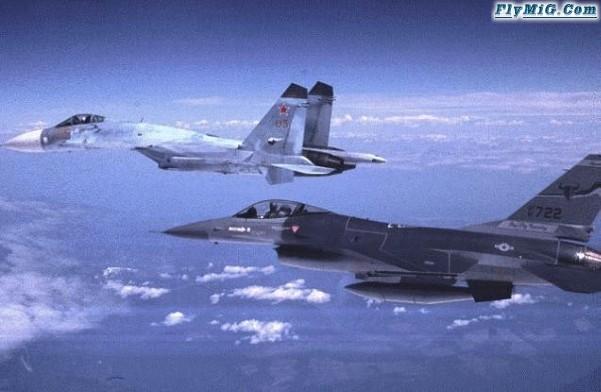
The Rafale for example has D shaped inlets that coupled with the shaping of its fore fuselage help it at high AoA in a similar way to the F-22 or Ching Kuo IDF
Both the Eurofighter and J-10 deviated from the F-16 in the use of close couple canards instead of LERXes but undoutedly are inspired by the F-16 aerodynamic layout, the rafale in that sense is a more original and sophisticated aircraft
Rafale Optimisation: ElementAir mon cher Watson!!!
Rafale optimisation is not a vain word or empty commercial argument.
The aircraft aerodynamic is way more developed than that of the previous design, the Rafale A.
After Rafale A flew first on 4th July 1986, it served its purpose as demonstrator, validating the close-coupled delta-canard formula.
In particular, it meet all of ACX requierements for high maneuvrability and STOL performances, climb rate, sustain dash speed etc.
The proposed Navalised version, ACM was to meet more stringuent requierement from Marine Nationale after a Carrier trial period:
Increased sink rate with a 16* AoA and better downward visibility than the A were among MN demands after Carrier trials.
Design have to evoluate further and Dassault designers didn’t do things half-way.
http://img123.imageshack.us/img123/8…filesuppp0.jpg
The A wings were similar to that of the Mirage IIING, a crancked delta plan which allowed the A to sustain M 2.0 and provided with good qualities at high AoA.
http://img260.imageshack.us/img260/6…ingplanjg3.jpg
In some instances (as in the case for the EAP), this wingplan can lead to assymetric dispacement of Cl at supersonic speed, the center of lift of the two parts of the wings moving back backward at a different rate. (It depends on wingsweep).
There were also gains to be made by repositioning the wings from low-shoulder to mid-fuelage and this unlocked several other design options starting with a reduction in wave drag:
http://img171.imageshack.us/img171/3229/hybridgs9.jpg
1) This allowed the designers to give the aircraft a sharply sweept LEX which not only gives an increae in lift but also is shaped for supersonic performances.
2) The surfaces of the canard was increeased by 30* and their root shaped so that they can deflect fully at 30* and increase the effect of the deflected airflow above the wing.
3) The LEX leading edge were designed sharper with a tri-dimentional shape, a constant sweept and progressive adrenal.
http://img379.imageshack.us/img379/2…evelopefk0.jpg
The LEX are rooted at the point where the inlets diffuser shock hits the inlet leading edge, and beneficiate from the same weaker shock wave which triggers their own while minimising its intensity.
http://img124.imageshack.us/img124/1733/vortexesdp1.jpg
At lower speeds they provoc several vortexes, one of which is clearly visible here, resulting on a significant increase in lift.
4) There was a marqued increase in wing-fuselage junction volume too, with a more blended shape which reduces wave drag and increases internal fuel volume.
Accessorly this feature is also reducing the aircraft RCS.
http://img69.imageshack.us/img69/5038/c01hybridkn3.jpg
While this would have been more than enough for most design houses, it wasn’t so for the Dassault aerodynamicians.
During the Mirage 4000 flight-tests, they notices that the nose cone and front fuselage could be used to accomodate better pressure control and increase overal aerodynamic efficiency around the inlets.
http://img46.imageshack.us/img46/649…eafronths5.jpg
This resulted in the characteristic V-shaped fron fuselage and inlet arrangement which optimises the airflow in front of the diffusers.
http://img296.imageshack.us/img296/1…leb3011dn2.jpg
http://img47.imageshack.us/img47/9974/rafrontbe7.gif
This arrangement allows for a higher supersonic performances and a less complex inlet design.
But AGAIN this wasn’t enough for Dassault, when they were given the word “OPTIMISEZ”!!!
Using their experience on the Mirage series they developed the conceipt of pressure and wave control even further:
Using the principes of compressive and expensive waves they channeled the boundary layer to the exact point where they wanted these phenomenons to occur: At the limit of the wing root.
There are several advantages in doing so:
First they do away with the Mirage 2000 strakes, as they are notably unstealthy and offers less control over the boundary layer.
These are normaly rooted at shoulder-level and dynamises the airflow around the fin at high AoA offering increased Yaw stability.
In the case of Rafale, by shaping the inlets in a V, they made it possible to energize BOTH that of the wing at its root and the fin’s simultaneously, retain a sleek aircaft and low RCS.
http://img183.imageshack.us/img183/5…ngementnh9.jpg
These shock takes place from the transonic regime, at point A where the airflow is separated, (part of it recycled by the engine IR-suppressant channel).
The shock created there is of the compressive type, and results on an increase in temperature, pressure and density, the airflow velocity becoming lower which means higher energy.
From point D and E, where it matters most, this same airflow is submited to another Shockwave, this time of the Expensive type.
http://img252.imageshack.us/img252/6682/condiii1.jpg
A new Mach line is created, resulting on lower pressures, density, temperature but a higher velocity which energises the airflow coming from the canard surfaces and the rest of the airframe.
This particular feature works so WELL thats its effects can even be seen when the aircraft is stationary due to paint tear and wear.
http://img441.imageshack.us/img441/1…irframeoq6.jpg
So to finish, the Supersonic optimisation of the wing.
Many tends to think that a 50*+ sweept angle would allow for better “performances”.
Well it’s true and untrue at the same time, the wing of a Mirage 2000 will drag more and have a lower lift coefficient at higher AoA.
There are advantages for higher sweept wings, higher Critical Mach is one but you need an accordingly overal reduced drag wave to take advantage of this.
For example: Mid-fuselage mounted wings and well blended fuselage wings areas, Rafale have this too…
Lower mid-to-high supersonic drag is another but this can be CONTROLED with different design features.
http://img47.imageshack.us/img47/3638/chocsli8.jpg
This is a composite image from different sources. One being NASA.
It shows the use of their little gizmo called ShockModeler and when applied to an aircraft design can bring a FEW surprises.
In the case of Rafale it appears that the designers have managed a “tour de force”:
They combined the effect of both the LEX and wings shockwaves in a way that it reduces its supersonic drag where the moderate 48* sweep angle would be the most needing it = Above M 1.65.
As shown in this image, the shock wave from the LEX creates a second zone (2 in purple) ahead of the wing leading edge.
Schock_M1.674.jpg. http://img127.imageshack.us/img127/8…ckm1674eg9.jpg
This appears from <> M 1.655 and doesn’t change from M 1.8 (as shown here) to speed well in eccess of M 2.0.
Schock_M2.0.jpg. http://img171.imageshack.us/img171/7…hockm20eq1.jpg
Before that due to their combination BOTH LEX and WING shockwaves are perpendicalar to the relative wing and are called “NORMAL”.
This compresses the whole design transonic zone, and reduces its transonic and supersonic drag further = increased optimisation.
The SMART bit is that the combination of the TWO waves are hitting the JUNCTION between the LEX and the wing (Hence the LEX particular frontal design) parralel to the ambiant air from <> M 1.674, where supersonic drag gets higher.
http://img379.imageshack.us/img379/2…evelopefk0.jpg
This results on the creation of two other zones, one (zone 3) adopting the characteristics of the free airflow, the fourth resulting from a NEW and weaker shockwave (Expension) created by its interection with the previous.
The limit between the zones 3 and 4 is called Slip Surface and is parralel to the wing leading edge.
This artificially incereased the high mach characteristics of the main wing by lowering the pressures while increasing the airflow velocity in front of the leading edge and reducing the shock intensities… = Expansion wave AGAIN.
As a result, the LEX can bedesigned with a much higher sweep angle which if it reduces their surface doesn’t result on a lower increase in LIFT, particularly so at higher Mach.
When was the last time someone asked WHY would Rafale have a higher payload and 250 nm better range with 3 X 2.000 L than a F-35 CLEAN while flying at a similar cruising speed?
Apparently, when some are buzy screwing their weight targets while CATIA, at Dassault they’re buzy doing the best job an aerodynamicist can do with it and then some…
I think it’s time to stop claiming superiority for somne designs which feature only (and comparatively) caterpilar-like aerodynamics.
Chapeau messieurs!!! http://img46.imageshack.us/img46/96/asterix01bu8.gif
“In Rafale the angle of attack is 16° but it can fly easily at 30° . Deck landings in the past were very stressful for the pilot. Now [in the Rafale] they are easy.”
http://img402.imageshack.us/img402/6469/0630190ve9.jpg
Chief test pilot Yves Kerherve.
source http://www.defencetalk.com/forums/showthread.php?t=6318
MiG-23MLDMiG-23MLD, you are undoubtedly aware of the fact that there are both General Aviation and Commercial Aviation-fora on the Key Publishing board. If you want to discuss Mexican advances in either of those areas, i suggest you post them there. I will leave this thread here on behalf of the drone, but please use the proper fora next time around.
Thank you.
I do understand that however there are two points that probably you do not know, Mexico`s current trend has indeed military applications, in fact Lockheed does do some outsourcing of the F-22 and F-16 electric harnesses in Mexico, Boambardier also does manufacture the Astor a military product and also the electric harnesses are built in Mexico, some MD helicopters are used by minor air forces and Mexico`s naval forces uses some MD helicopters, GE also does design and manufatures in Mexico parts and spares for military aircraft engines in few words despite it is boring for many, the Mexican aircraft industry is very involved in supplying the US military machine with aircraft parts
“burning platform” existed within the electrical harness fabrication department at Lockheed Martin Aeronautics Company – Fort Worth (LM Aero – FW). During the Engineering and Manufacturing Development phase of the F-22 program, a decision was made to offload the fabrication of electrical harnesses for the F-22 mid-fuselage to Mexico. The Fort Worth jobs for this task were going away. The workers in the fabrication area teamed up to fight to retain the work and their jobs. The F-22 program office, whose responsibility is to provide value, affordability, and capability to the customers, the U.S. Government and the warfighter, issued a daunting challenge to the team: lower the cost. This meant reducing the labor hours it takes to build the product by 74 percent, which was by no means an easy challenge. Furthermore, there would only be one shipset of product available to demonstrate the reductions: a steep learning curve indeed. A radical departure from business as usual needed to occur at LM Aero – Fort Worth, “business as usual” just wasn’t going to cut it.
source http://www.wiringharnessnews.com/Articles/2000/F22/f22.htm
“In Chihuahua City, Lockheed makes F-16 harnesses. When people come to see us, we like to take them to that shelter. It is outstanding, and it expanded recently.
“Juarez is the harness center of the world,” Barrett added. “We’ve had experience with this going back to 1976. That ensures a high-skilled labor force. So they keep coming
source http://www.expansionmanagement.com/cmd/articledetail/articleid/15057/default.asp
here we have some other interesting mexican design the rocket belt built by TAM or Tecnologia aerospacial Mexicana


Some important achievements:
The first and only in the world to built totally from scratch a Rocket Belt producing every part and the machine to produce our own rocket fuel.
Isabel Lozano, the first and only woman in the world that have flown a Rocket Belt. (See the Media menu for all the magazines and TV programs around the world about us)

some of the clients of TAM are the USAF
http://www.tecaeromex.com/ingles/clients.htm
sourcehttp://www.tecaeromex.com/ingles/indexi.html
MiG-23MLDFirst Challenger 850 Fuselage Made in Bombardier’s New Mexican Facility
Querétaro, Mexico, January 11, 2007 – Today Bombardier Aerospace celebrated the shipment of its first Mexican-built Challenger 850 fuselage to its Montreal facility for final assembly.
Present in the ceremony were the Mexican Bombardier Aerospace employees, Eduardo Sojo Aldape, Mexico’s Secretary of Economy, Francisco Garrido Patrón, Governor of the State of Querétaro, Flavio Díaz Mirón, Bombardier Chief Country Representative, and Réal Gervais, Bombardier Vice President Manufacturing Center Mexico.
MiG-23MLDMore pictures of the Bombardier challenger 850 being built in Mexico and former President Fox on the picture

http://fox.presidencia.gob.mx/actividades/crecimiento/?contenido=26571

http://fox.presidencia.gob.mx/actividades/crecimiento/?contenido=21546

http://www.queretaro.gob.mx/noticia.php?historico=true&clave=2944&pageNum_noticias=590
This link is to see some MC donnel douglas helicopters built in mexico
http://www.foroclusters.com/ConferenciasVivo/Documentos/9%20Aero%203%20Veronica%20Orendain%20SE.pdf
One of the few military helicopters to have been assembled in Mexico by the Mexican Navy
http://portalaviacion.vuela.com.mx/imgarticulos/comentarios/03com.jpg

MiG-23MLDWhat do you guys think about the Mitsubishi F-2?
Clearly based upon the F-16/Agile Falcon.
I remember seeing early artist concepts of the F-2 (then FS-X) with canards – similar to the F-16 AFTI.
I think the Mitsubishi F-2 has still got a lot of development potential. Maybe a future air-air version could have canards, like the original pics for improved manoeuvrability.
But, as has been discussed at length in other threads, Japan has its sights on the F-22.
Static Margin
The definition of neutral point leads to a very convenient and commonly used alternate criteria for static longitudinal stability. It is clear from (6.10) and (6.17) that locating the center of gravity at the neutral point gives the aircraft neutral stability, moving the center of gravity forward of the neutral point produces positive static stability, and moving the center of gravity aft of the neutral point makes the aircraft statically unstable. An alternate criterion for positive static longitudinal stability, therefore, is that the center of gravity is forward of the neutral point. This criterion is normally stated in terms of the aircraft’s static margin, S.M., which is defined as:
(6.18)
Stated in terms of static margin, the stability criterion becomes S.M. > 0. Static margin is a convenient non-dimensional measure of the aircraft’s stability. A large static margin suggests an aircraft which is very stable and not very maneuverable. A low positive static margin is normally associated with highly maneuverable aircraft. Aircraft with zero or negative static margin normally require a computer fly-by-wire flight control system in order to be safe to fly. Table 6.1 lists static margins for typical aircraft of various types.
Table 6.1. Static Margins for Several Aircraft
Aircraft Type Static Margin
Cessna 172 0.19
Learjet 35 0.13
Boeing 747 0.27
North American P-51 Mustang 0.05
Convair F-106 0.07
General Dynamics F-16A (early) -0.02
General Dynamics F-16C 0.01
Grumman X-29 -0.33
As a final comment on static margin, it is interesting to note the relationship between static margin, lift curve slope, and moment curve slope. An inspection and comparison of (6.10), (6.17), and (6.18) reveals:
(6.19)
Altering Stability
The discussion of neutral point began with considering how moving the center of gravity location would change an aircraft’s static longitudinal stability. Equation (6.10) can be used to predict how other changes in an aircraft configuration will alter its stability. For example, suppose the value of wing/strake/fuselage lift curve slope, , is increased by increasing the wing aspect ratio, the strake size, or the wing’s span efficiency factor. If, as in most conventional aircraft, the aerodynamic center of the wing/strake/fuselage combination is forward of the aircraft center of gravity so that xcg – xac. > 0, then increasing makes the wing term in (6.10) more positive. therefore becomes less negative, and the aircraft less stable. For an aircraft configuration where xcg – xac. < 0, on the other hand, (6.10) shows that increasing increases static stability. Table 6.2 lists several other common aircraft configuration changes and the effect they have on stability.
Table 6.2 Aircraft Changes Which Affect Stability
The change in the static marging is due to a different taiplane
here is the math
(6.10), (6.17), and (6.18) reveals:
(6.19)
Altering Stability
The discussion of neutral point began with considering how moving the center of gravity location would change an aircraft’s static longitudinal stability. Equation (6.10) can be used to predict how other changes in an aircraft configuration will alter its stability. For example, suppose the value of wing/strake/fuselage lift curve slope, , is increased by increasing the wing aspect ratio, the strake size, or the wing’s span efficiency factor. If, as in most conventional aircraft, the aerodynamic center of the wing/strake/fuselage combination is forward of the aircraft center of gravity so that xcg – xac. > 0, then increasing makes the wing term in (6.10) more positive. therefore becomes less negative, and the aircraft less stable. For an aircraft configuration where xcg – xac. < 0, on the other hand, (6.10) shows that increasing increases static stability. Table 6.2 lists several other common aircraft configuration changes and the effect they have on stability.
Table 6.2 Aircraft Changes Which Affect Stability
6.7 STABILITY AND CONTROL ANALYSIS EXAMPLE: F-16A and F-16C
Figure 6.15 illustrates an early model F-16A and a later F-16C. The differences between the stabilators of the two aircraft are apparent. The increase in stabilator area was made to all but the earliest F-16As to increase pitch control authority. Table 6.3 lists descriptive data for each aircraft.
The stability analysis begins by estimating the location of the aerodynamic center of the wing/strake/fuselage combination, which will be the same for both aircraft. For the F-16 wing alone:
l = ctip / croot = 3.5 ft /16.5 ft = 0.212
= 11.4 ft
= 5.875 ft
xac = yM.A.C. tan LLE + 0.25 M.A.C. (subsonic)
= (5.875 ft) tan 40o + 0.25 ( 11.4 ft) = 7.8 ft
x ac = yM.A.C. tan LLE + 0.50 M.A.C. (supersonic)
= (5.875 ft) tan 40o + 0.50 ( 11.4 ft) = 10.6 ft
Table 6.3. Descriptive Parameters for an Early F-16A and an F-16C
Item Early F-16A F-16C
Wing:
S, ft2 300 300
croot, ft 16.5 16.5
ctip, ft 3.5 3.5
b, ft 30 (no missiles or rails) 30 (no missiles or rails)
x of root chord leading edge, ft 0
(20 ft aft of fuselage nose) 0
(20 ft aft of fuselage nose)
LLE, degrees 40 40
Stabilator:
St, ft2 108 135
croot, ft 10 11
ctip, ft 2 3
b, ft 18 18
x of root chord
leading edge, ft 17.5 17
LLE, degrees 40 40
Strake (exposed)
Sstrake, ft2 20 20
croot, ft 9.6 9.6
ctip, ft 0 0
b, ft 2 2
x of root chord
leading edge, ft -8 -8
LLE, degrees (avg.) 80 80
Fuselage
lf 48.5 48.5
wf 5 5
Whole Airplane
(relative to M.A.C.) .35 .35
Adding the effect of the strake:
lstrake = ctip / croot = 0 ft /9.6 ft = 0
= 6.4 ft
= 0.33 ft
xacstrake = yM.A.C.strake tan LLEstrake + 0.25 M.A.C.strake (subsonic)
= (0.33 ft) tan 80o + 0.25 ( 6.4 ft) = 3.5 ft
x acstrake = yM.A.C.strake tan LLEstrake + 0.50 M.A.C.strake (supersonic)
= (0.33 ft) tan 80o + 0.50 ( 6.4 ft) = 5.1 ft
but these are defined relative to the leading edge of the strake root chord, not the wing root chord. From Table 6.3, the strake root is 8 ft forward of the wing root, so relative to the wing:
x acstrake = -4.5 ft (subsonic)
x acstrake = -2.9 ft (supersonic)
and:
= 6.5 ft (subsonic)
= 9.1 ft (supersonic)
Now, adding the effect of the fuselage, using Cla wing/strake = 0.068/o (predicted in Section 4.7) and the fact that the wing root leading edge is 20 ft aft of the fuselage nose, so that lacwing/strake = 20 ft + xacwing/strake :
= 6.4 (subsonic)
To perform the supersonic calculation, supersonic lift curve slope must be predicted. A specific Mach number must be chosen. For M = 1.5:
= 0.051/o
= 9.0 ft (supersonic)
Next, the aerodynamic center of the F-16A stabilator is located:
lstabilator = ctip / croot = 2 ft /10 ft = 0.2
= 6.9 ft
= 3.5 ft
xacstab = yM.A.C. stab tan LLE stab + 0.25 M.A.C. stab (subsonic)
= (3.5 ft) tan 40o + 0.25 ( 6.9 ft) = 4.7 ft
xacstab = yM.A.C. stab tan LLE stab + 0.4 M.A.C. stab (supersonic)
= (3.5 ft) tan 40o + 0.50 ( 6.9 ft) = 6.4 ft
These are defined relative to the leading edge of the stabilator root chord. From Table 6.3, the stabilator root is 17.5 ft aft of the wing root, so relative to the wing:
x ac stab = 22.2 ft (subsonic)
x ac stab = 23.9 ft (supersonic)
But the distance of interest for the stabilator is lt, the distance from the stabilator’s aerodynamic center to the aircraft center of gravity. Table 6.3 lists the center of gravity as 0.35 M.A.C., so relative to the wing root:
xcg = yM.A.C. tan LLE + 0.35 M.A.C.
= (5.875 ft) tan 40o + 0.35 ( 11.4 ft) = 8.9 ft
and:
lt = x ac stab – xcg = 22.2 ft – 8.9 ft = 13.3 ft (subsonic)
= 23.9 ft -8.9 ft = 15 ft (supersonic)
It is now possible to calculate tail volume ratio:
= 0.42 (subsonic)
= 0.47 (supersonic)
Recall from Section 4.7 that 0.48. Since the F-16’s is specified relative to the leading edge of the M.A.C. it is convenient (and common) to express and relative to the same reference. This requires subtracting the distance between the root leading edge and the M.A.C. leading edge from the value of xac. The expression for then becomes:
subsonic
supersonic
So that the F-16A’s static margin is:
= 0.33 – 0.35 = -0.02 subsonic
= 0.58 – 0.35 = +0.23 supersonic
Similar calculations for the F-16C yield
S.M. = 0.36 – 0.35 = +0.01 subsonic
S.M. = 0.61 – 0.35 = +0.26 supersonic
Figure 6.16 plots the neutral point locations calculated for the F-16C vs Mach number and compares them with actual values. Note that, despite the F-16’s relatively complex aerodynamics, the method produced reasonably good estimates.
General Dynamics F-16A (early) -0.02
General Dynamics F-16C 0.01
as you can see the increase in the size of the tailpalne affects the general stability of the F-16 series we can expect something similar happens with the F-2 since it has a different wing and tailplane configuration
MiG-23MLDWhat do you guys think about the Mitsubishi F-2?
Clearly based upon the F-16/Agile Falcon.
I remember seeing early artist concepts of the F-2 (then FS-X) with canards – similar to the F-16 AFTI.
I think the Mitsubishi F-2 has still got a lot of development potential. Maybe a future air-air version could have canards, like the original pics for improved manoeuvrability.
But, as has been discussed at length in other threads, Japan has its sights on the F-22.
From my humble opinion the F-2 is not a very radical version of the F-16, in fact is only a little bit modified F-16 built under license by Japan
Some differences in the F-2 from the F-16A:
a 25% larger wing area
composite materials used to reduce overall weight and radar signature
longer and wider nose to accommodate a phased-array radar
larger tailplane
larger air intake
three-piece cockpit canopy
capabilities for four ASM-1 or ASM-2 anti-ship missiles, four AAMs, and additional fuel tanks
MiG-23MLDUAE Block 60s win here on every occassion 😉 With all the stuff on them they look almost unreal.. With full loadout, CFTs and dorsal spine I wonder whether the thing still has some aerodynamics at all 😉 Absolutely cool…
Each aircraft has its trade offs and gains, for example the LERXed F-16 might not be very different to the canard delta J-10 in performance, however the CFT probable unpair the latest F-16s agility, something that seems to do not matter thanks to missiles like the AIM-9X or Python 5.
The J-10 seems to show features more of an interceptor since its canards and inlet suggest a trade off for speed and STOL to a certain extend in exchange for sustained turn rate; however it might have a better instantaneous turn rate see
wind tunnel testing and project work on alternative aft tailed configurations had pointed out many advantages for that particular layout, where perhaps range and sustained turn rate were the most noticeable
The aerodynamic advantages derived from the close coupled canard configuration, foremost its good vortex flow stability up to high angles of attack (AOA), that can be translated into a very high instantaneous turn rate, and which in conjunction with pivoting canards that are automatically trimmed to give optimal lift-to-drag (L/D) ratios for all cg positions,
Adopting negative stability means that the center of gravity (cg) can be placed well back behind the aerodynamic center, which in turn for a canard layout opens up a greater degree of freedom in arranging the installation of internal systems and engine in such a way that an optimal cross sectional area distribution and thus low supersonic wave drag at the selected Mach number value, can be achieved
The wing can be located more forward on the fuselage and a long and slender tail cone, quite unlike the abrupt ending found on the Viggen, and without the horizontal tail adding unwanted volume to the area distribution, can be designed. This will contribute to a low aft body drag, and will also offer an extremely good position for large efficient air brakes, exhibiting marginal trim transients when deployed
This is a contrasting fact of the J-10 with respect the Gripen, the J-10 has a more draggy aft section than the cleaner JAS-39 with its twin ventral fins ala F-16
http://www.mach-flyg.com/utg80/80jas_uc.html
CLOSE-COUPLED CANARDThe aerodynamic advantage derived from the close-coupled canard configuration is its good vortex flow stability up to high angles of attack (AOA) that can be translated into high instantaneous turn rates of up to 30º/sec and which, in conjunction with the pivoting canards that are automatically trimmed, provides optimal lift-to-drag (L/D) ratios for all CG positions, Mach and AOA. For aerodynamicists, there are two mechanisms available for augmenting the stability and control at high AOA, namely, the canard or the strake. For SAAB, the choice of configuration, canard or tail, was initially far from obvious, but a substantial body of knowledge on the delta-canard layout, gained from its Viggen experience, existed. The delta-wing’s most appealing aerodynamic feature is its stable vortex flow up to very high AOA which provides a high maximum lift coefficient. When coupling a canardwith the delta-wing, the canard generates a stable, detached leading edge vortex that interferes favourably with the vortex flow from the main wing and they mutually reinforce each other, thereby delaying the vortex burst to a much higher AOA than a delta wing on its own would do.This fact was well known to aerodynamicists worldwide, but the Americans instead opted for using large strakes as forward wing root extensions together with the conventional tail arrangement such as those found on the F-16 and F-18. Although this may seem strange,it bears mentioning that the canard is most effective when coupled to a delta wing while strakes are more effective when used in conjunction with non-delta wings. The flow physics and the aerodynamic principles involved are essentially the same for a strake and a canard except that a canard can be made moveable and thereby actively contribute to aircraft control throughout the flight envelope. The canards on the Gripen are, therefore, fully movable and together with the elevons, provide the Gripen the optimum combination of manoeuvrability.The strake, on the other hand, is fixed and contributes only at the higher angles of attack.It is rather surprising then that the USA has never really elected to go for the canard despite the fact that the rest of the world has demonstrated their faith in the canard.This is not to say that the Gripen does not utilise strakes. In fact, a pair of small strakes is fitted behind the canard surfaces to augment the airflow and enhance the directional and lateral stability at high AOA, so vital for the dogfight. This aerodynamic fix is also used on the Eurofighter and the Mirage 2000.The major disadvantage of fixed strakes is that they do not permit the designer to maximize the benefits arising from a movable canard. By using an active canard, SAAB has managed to optimise not only the handling qualities and stability and control, but also take-off and landing performance.
http://www.gripen.hu/download/18.10948cf10331003a2d8000805/GripenMay2005.pdf
MiG-23MLDSure the F-15E is in a different league than a F-16 Blk 50/52+. People loading up their F-16 with CFTs, underwing tanks, heavy stand-off weaponry, etc etc seem to have a long range strike mission in mind. (In case of that picture showing the HAF F-16s it’s just a pissing contest with the Turks, because in the real world HAF will never bomb Ankara). And in the case of the rich-n-wanton Arabs, they will never bomb Tehran, but if they ever did, a F-15E would be more useful because it’s range/capabilities equation far out there is much better.
I think the F-16 is not a F-15E counterpart, only the Su-27 can be called an F-15E equivalent however the Su-27 is a semi hybrid of the F-15 and F-16.
The Su-27 and F-16 are quit comparable, in fact besides the fact the Su-27 has two engine nacelles, twin tail fins and variable geometry highly raked inlets both aircraft basicly share a common configuration.
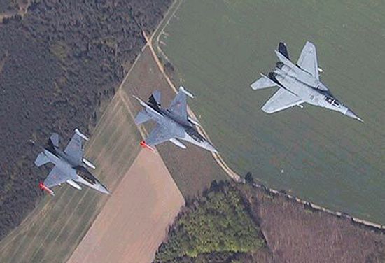
same we can say about the MiG-29.
The J-10 to the contrary is the real equivalent of the F-16, however it adopted the delta canard configuration to achieve the best compromised in aerodynamics instead of the LERXed tail configuration of the F-16.
MiG-23MLDFirst fuselage of a Bombardier Challenger 850 delivered by the Mexican plant
source http://www.skyscrapercity.com/showthread.php?t=386303
MiG-23MLD. MARKET OVERVIEW
Most companies that make-up the aerospace industry in Mexico are foreign owned. The industry is comprised of approximately 60 companies with the largest concentration in the northwest region of Mexico:
A. Baja California
Thayer Aerospace
Lockheed Martin
Volare Engineering
Gulfstream
Cal Pacifico
Crisair Inc
GKN Aerospace
Suntron
Cubic Corporations
Northrop Grumman
OSCA-ARCOSA
Orcon Corproration
Rockwell Collins
Delphy
Hartwell Dzus
Pratt & Whitney Canada
Helair International
Pacific Miniatures
B. Chihuahua
Honeywell
Labinal
Delphi
C. Nuevo Leon
FRISA – Wyman Gordon
KAYDON
D. Coahuila
General Electric
Parkway products Inc.
Unison
E. Jalisco
GlobalVantage
Cadimex
F. Mexico City
MODINE
G. Queretaro
Honeywell
ITR
H. Tamaulipas
Parker
Modine
I. San Luis Potosi
Teleflex
Sermatech
Tighitco
J. Sonora
Chem Research Company Inc.
TEXTRON
Goodrich
G.S. Precision Inc.
Smith West Inc.
Parker
ESCO
Tolerance Masters
Sargent
K. Yucatán
Falco Electronics
Precision Castparts Corp.
In the off shore Guaymas Industrial Park, where precision machined components for aircraft engines are made, there are about 12 aeronautics companies with an important nucleus of capability. The companies are non-competitors and complementary in a positive manufacturing environment.
2. MARKET TRENDS
Aerospace parts manufactured in Mexico include; turbine, fuselage and landing gear components, plus harnesses and cables. There are also audio and video systems, heat exchangers, as well as some interior parts such as bathrooms and galleys.
Most aeronautical parts and components made in Mexico are intended for the U.S. market and export figures provide the best performance measure for this industrial sector. Product sales were flat at about US$50 million annually through 1997, but in 1998 exports rose to US $ 144 million. Eventually they reached US$ 350 million by 2003.
Aerospace components made in Mexico and exported to the U.S. are expected to top half a billion dollars during 2006. This is a ten-fold increase over the last 10 years and positions Mexico as the tenth largest foreign supplier of aerospace goods to the U.S. although it is still far away from more mature suppliers such as Canada, France, United Kingdom and Brazil.
Mexico manufactures just 2 percent of the approximately US$25 billion US import market and growth prospects look promising. Some sub-industries have experienced a growth of over 20 percent in the last business year. An important fact that influences the growth rate is the companies’ ability to undertake the 10-12 month training of machine operators.
Companies such as ITR in Queretaro conduct turbine maintenance and repair services. Pratt and Whitney in Tijuana repair high-tech composite materials parts.
Aerospace design and engineering activities are also taking place in Mexico. In Coahuila state, there is GE’s Center for Advanced Engineering in Turbo machinery, a place where Mexican engineers are designing control systems for jet engines.
3. COMPETITION
Mexico provides advantageous conditions for the U.S. aerospace industries. The aerospace manufacturing requirements and Mexico’s conditions are attractive: low-cost manufacturing, in high/mix-low/volume production conditions along with intellectual property protection and near shore logistics advantages. However, other countries, such as Canada, may prove to be able to compete as well. Thanks to Canada’s generous Research & Development tax breaks, companies in Canada may deduct 100% of their R&D expenses. The program is permanent and the credit is refundable (if the company is not making a profit). Salaries, materials and even equipment qualify. As a hoped for result, Canada’s aerospace industry invests approximately US$700 million a year in R&D.
4. MARKET FUTURE
Mexico needs a long-term plan to cater to the aerospace industry’s vast potential, and at the same time accommodate its demanding manufacturing conditions. Such a plan requires highly coordinated public and private policies, in addition to sufficient patience to obtain a critical development mass in the aerospace industry such as that of Canada ‘s and Brazil’s.
Mexico is currently at the early stage of a hypothetical model for development of the aerospace industry. It manufactures individual parts and components, and could later make progress toward the assembly of systems or structures to stage II (i.e. landing, control). Eventually it could work its way into the full assembly of aircraft in the third stage.
This process may take between 8 and 25 years, depending on the speed and quality of conditions facilitated in a given country. Maturity beyond aircraft assembly is in the design, engineering and manufacturing of key components such as turbines. This is a development stage reached only by a few countries.
5. MEXICO – U.S. AGREEMENTS
BASA- Under current Federal Aviation Administration (FAA) rules, manufacturers in Mexico are not able to certify parts as airworthy. Therefore, aerospace parts and components made in Mexico must be shipped to the US for inspection at a domestic facility before being shipped to US customers. In order to obtain certification rights, a treaty known as a bilateral aviation safety agreement (BASA) between Mexico and the U.S. is required.
The Mexican government is finalizing an agreement for manufacturers and industry institutional organizations. The long awaited agreement should become a reality soon, reportedly before the end of 2005.
In order to fully maximize the potential of manufacturing and repairing of aerospace parts in Mexico, the signature of BASA is required. This would not only reduce costs, but it would also strengthen the trust of the sensitive aerospace industry in Mexico.
Also, even though BASA is the primary need, obtaining access to agreements such as “The Defense Production Sharing Agreement” and the “Defense Development Sharing Arrangement” would provide Mexico access to military projects.
6. INCENTIVES
Being a high-risk and strategic industry, aerospace development has always been supported significantly by the governments of the host countries. Be it Embraer in Brazil, Bombardier in Canada, Boeing in the US or Airbus in Europe, country governments significantly underwrite operations with monetary and non-monetary participation and incentives. These include items like venture capital, tax reductions, preferential loans, academic scholarships and contracts.
Mexico must be prepared to provide global competitive support to the aerospace industry if it wishes to reach the integration phase of development and advance to aircraft assembly.
7. AIRPORTS
In Mexico, airports are perceived as just that, airports. In the US, and more so in Europe, airports constitute the nucleus of a whole master plan for business, manufacturing and services development. Mexico needs to take its airports a step further by upgrading their site concept, improving their planning and urban development, and fostering other services and activities around them.
Development of the Airports sector has been a priority for Mexico’s Federal Government. After September 11, the Aviation and Airport industry worldwide suffered greatly. Nonetheless, from 2003 to 2004, total airport demand for imported equipment and services increased 9.8 percent and U.S. exports grew 9.7 percent. Main competitors are French, British, German and Canadian companies.
Total Airport Equipment Demand in millions of US dollars
2002 2003 2004
Total Market Size 10,503 9,617 11,457
Total Local Production 2,105 2,290 2,496
Total Exports 2,360 2,226 2,621
Total Imports 10,758 9,553 11,582
Imports from the U.S. 9,682 8,597 10,423
Source: 1. Communications and Transportations Secretariat (SCT), Statistics annual book. 2.SCT’ s North American Transportation Satistics.2. Aeropuertos y Servicios Auxiliares (ASA) Statistics 3.National Institute of Geographical and Statistic Data (INEGI). 4.World Trade Atlas (BANCOMEXT). 5. Secretary of Economy.
Note: Total imports in years 2002 and 2003 reflect inventory carry-over by end users, thus they are bigger than the Total Market size.
Airports equipment includes: 1. Electronic integrators. 2. Printed circuits. 3. Parts for engines. 4. Electric capacitors. 5. Lamps & Airfield lightning. 6. Radar Apparatus & Navigation systems. 7. Baggage and cargo lifting and handling systems, conveyors and equipment. 8. Air-conditioning, Control, Regulation and Energy Conversion. 9. Airport Security Sound & Camera Systems. 10. Cargo Loaders, Fork Lifters, Work Trucks and Self-Propelled Passenger carriers. 11. Aircraft Launch Gear. 12. Management Consulting Services.
On the other hand, the Mexican airport industry size has grown by U.S. 800 million between 1998, when it was privatized, and 2002. This is an average growth rate of 10 percent annually, although Mexican government investment in the airport industry suffered major cuts. From 1998 to 1999, government investment declined 48 percent and in 2000 government investment was down to U.S. 256.7 million. In 2002, government investment had grown to U.S. 271 million.
On the services side, Mexico’s international cargo trade by air in 2002 was worth U.S. 21.6 billion and in 2003 it declined to U.S. 20 billion. During the same period, the inbound and outbound trade cargo with the United States was U.S. 9 billion and U.S. 7.4 billion respectively.
During 2002, imports alone of all goods from the U.S. made through the Mexican airport network were U.S. 4 billion, which represented 3.8 percent of the total imports made by any mode from the U.S. in that year. In 2003, imports by air from the U.S. were U.S. 3.7 billion, which represented 3.5 percent of total imports by any transportation mode from the US.
Freight activity through Mexican airports in 2001 was 107,000 metric tons, of which 10,000 MT were domestic and 97,000 MT were international. In the year 2002 the volume was reduced to 99,000 metric tons (15,000 MT domestic and 84,000 MT international). During 2003, the volume was 86,000 MT with 19,000 MT domestic and 67,000 international. The rapid decline of international air cargo may be compensated by an increase of road and rail traffic.
8. SPECIAL COMPONENTS
Aircrafts are made of materials, which are not common in Mexico ‘s industries today. Metals such as titanium, inconel, aluminum, and special alloys are hard to find. In addition, there ‘s a lack of expertise and skill in the founding, fabrication, forging and machining of specialized metals. Aerospace manufacturers will naturally seek those regions with competitive advantages.
9. UPCOMING TRADE SHOWS
Aeroexpo Aviation Trade Show April 18-20, 2007 – Biannual Show at the Santa Fe Conventions Center in Mexico City. This year’s show statistics are:
Over 170 companies and institutions participated representing more than 20 countries throughout the world.
Over 145 booths sold.
Over 15,000 accredited visitors.
More than 40 conferences held.
Exhibit area: More than 10,500 sq. meters.
Over 60 aircraft were exhibited at the static display in nearby Toluca.
7 helicopters were exhibited at Santa Fe Trade Conventions Center.
40 local and international media networks covered the show.
Representations of 10 Mexican States governments participated.
Mexico’s aerospace industry gets northern exposure By Marla Dickerson and Carlos Martinez LOS ANGELES TIMES Tuesday, May 29, 2007QUERÉTARO, Mexico — Building jet airplanes has long been the domain of advanced industrial nations. Now Mexico is trying to join the club by hitching a ride with a Canadian aerospace company.Montreal-based Bombardier Aerospace broke ground this month in this central Mexican city on a massive complex to build wiring harnesses, fuselages and flight controls. The company, best known for its Learjets and other executive jets, employs 450 here and plans to have 1,200 by the end of next year. Since it began production in temporary quarters in May 2006, Bombardier has hit the throttle. Its Mexican employees are cranking out subassemblies such as tail rudders two years earlier than the company had planned. Mexican officials project that Bombardier will start assembling complete planes here within five years. Company officials won’t make any promises. But it’s clearly on their radar screen. “There is no doubt in my mind that if we stay focused the way we are now . . . that (Mexico) can do the same as we do in Canada or Europe or the United States,” said Real Gervais, director general of Bombardier’s Mexican operations. If it comes to pass, Mexico would be one of the few developing nations doing final assembly of sophisticated planes. “This is the great objective that we all have, not only Querétaro, but the nation,” said Renato Lopez Otamendi, secretary of sustainable development for the state of Querétaro. Mexico’s aerospace industry comprises about 125 companies and 16,500 workers. Once little more than a low-cost job shop for U.S. aerospace suppliers, Mexico is handling increasingly sophisticated tasks. A General Electric subsidiary employs 500 aerospace research and development workers in Querétaro. MD Helicopters Inc. is manufacturing fuselages in Monterrey. Some large aircraft maintenance operations are setting up shop. U.S. imports of Mexican aerospace products totaled nearly $178 million last year, up 60 percent from 2000. Total aerospace exports topped $500 million in 2006, according to Mexico’s Economy Secretariat. Government officials want to keep Mexico moving up the supply chain. Although there is no talk of the government launching its own national program, officials say they want more high-value tasks from big companies, including structure and design work and final assembly. Mexico is fast losing basic industries such as textiles to nations with cheaper labor. So, Mexico is looking to capitalize on its success at building products such as automobiles. Aerospace carries a special cache. Countries that can build something as complex as a jetliner are viewed as having their industrial act together. “It’s a big deal,” said consultant John Walsh of Walsh Aviation. “But there are a lot of hurdles to getting into the big leagues.” Developing countries produced less than 10 percent of the aerospace parts imported by the U.S. last year.
http://www.bajaaerospace.org/Articles-Reports/0705-LATimes-MexPlanes.pdf
Bombardier`s Mexican plant is building at the present moment electric harnesses for the CRJ-700 and CRJ-900 regional jets and for the Challenger 300 and Global expresss executive jets besides Mexican workers are building the central fuselages of the Challenger 850 
http://seattletimes.nwsource.com/html/businesstechnology/2003723670_mexicoplanes27.html
MiG-23MLDCome on Distiller, you have to admit that a massively overloaded lawndart does look kinda cool and purposeful, especially the new Israeli birds.:diablo:
I kind of dislike the latests F-16s blocks, specially with CFT, i do not understand why the F-16CCV and the F-16MATV experimental varianst did not get into production, probably an F-16XL has more sense than the F-16E,
for example one of the advantages of the Gripen’s configuration is that it enables direct lift to be produced, by deflecting the canards in conjunction with the elevons, without rotating the aircraft. Like-wise, the foreplanes could be used differentially to create a side-force, which could be combined with rudder deflection to generate a lateral force without change of heading. Such ”un-coupled” flight modes may be useful in air-to-air gunnery or in the delivery of unguided weapons against surface targets, basicly the F-16CCV can do the same see The first YF-16 (72-1567) was rebuilt in December 1975 to become the USAF Flight Dynamics Laboratory’s Control Configured Vehicle (CCV). CCV aircraft have independent or “decoupled” flight control surfaces, which make it possible to maneuver in one plane without movement in another–for example, turning without having to bank.
. http://www.airtoaircombat.com/background.asp?id=8&bg=67
http://www.gripen.com/NR/rdonlyres/4894FED7-B3C4-43E6-A2D3-18555894C435/0/gripen_news_2000_02.pdf
http://www.eltanin.co.za/res/default/gripen_fighter.jpg

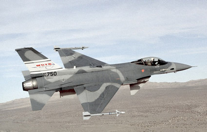
MiG-23MLDIt might be a little like a pimped stream engine (see 25NC 4-8-4), but in a way the F-16 is the ultimate conventional single engine fighter (conventional because one could do a pure flying wing with TVC, etc, etc) and still has a lot of life in the design: Take DSI, engines with AVEN/LOAN, new cockpit with HMDS, modern materials, sensors, weapons, and one would have all the counter-air capability one ever needs, sans stealth. But – pure fighters are not en vogue.
Of all the potential threats the F-16s are facing i would rank the J-10 as the closest aircraft with similar design.

for example very likely it has a ventral air intake because The ventral location for the intake most likely was chosen to minimize the sensitivity of airflow into the engine at high angles of attack like in the F-16`s case
also like the F-16, the J-10 also has ventral fins located under the aft section of the J-10’s fuselage that provide added stability during tight, high-speed turns, and are subject to high stresses from severe buffeting and turbulence
The MiG-29 did use ventral fins but deleted them thanks to its two vertical dorsal tail fins however the F-16 and J-10 chose single tail over twin fins this create less buffeting from strake or canard vortices at high alpha
Contrary to the F-16 that has a fixed engine inlet geometry that reduces TOGW, and limits the F-16`s Max speed at M<2, the J-10 uses a variable geometry inlet and this allows it very likely a higher speed than Mach 2
however The F-16 (like the MiG-29 and F-18) has LERXes these Leading Edge Extensions do provide controlled vortex lift; Produces lift on the inboard portion of the wing and straightens the flow over the outboard portion of the wing– Strake geometry and its interface with the forebody and wing were developed over many hours of wind tunnel testing of more than 50 configurations, this also generate a Net increase in lift at high angles of attack this extra lift is over 25 percen, the LERXes also reduce buffet intensity– and Improve directional stability. All of this Increases trimmed lift-to-drag ratio
In the J-10, its canard foreplanes do a similar job.
It is said the Eurofighter, MiG-29 and F-18 have better AoA handling than the F-16.
however i wonder if the current latest modification is the best to defeat the MiG-35, J-10 and Su-35 without considering the Eurocanards
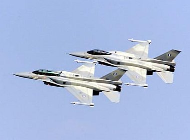


 Sign In