Bager1968
http://www.aarg.com.au/CA31.htm
CAC CA31
Operational Trainer – Full size mockup (on display) in the back of the Australian National Aviation Museum, at Moorabbin Airport near Melbourne, Australia. The mock-up is disassembled and against one wall (easily missed).
In March 1964, with the Mirage fighter being delivered to the RAAF, the Melbourne based Commonwealth Aircraft Corporation presented its idea for a locally designed and manufactured, advanced supersonic aircraft designed to meet both flying and weapons training needs.
The basis of the project was that there was no type with this dual capability available anywhere in the world. In the 1960s, it was also seen that there was a huge gap between flying jet trainers and modern high speed fighters. This difference involved more than just speed, the flying characteristics of supersonic delta wing fighters were quite different to the subsonic trainers then available.
The original design featured a double delta wing powered by a single GE – J85 engine (~3,000 lbst/~4,300 lbst AB), the design was advanced to the stage of constructing this full size mockup, and then revised to incorporate the Rolls Royce RB172 Adour engine.
The aircraft was to feature Martin Baker ejection seats and be capable of carrying a load of 1815 kg on four wing and two fuselage hardpoints.
The RAAF jet trainer requirement was eventually fulfilled in 1967 by Macchi Trainers licence built by CAC, and a number of 2 seat Mirages built by GAF in Melbourne, resulting in the CA-31 project being canceled, effectively ending CAC’s indigenous designs.
Engine: Rolls Royce RB172 Adour jet (4,600 lbst dry, 6,900 lbst reheat)
Length: 37 feet 8.5 inches (11.5 m)
Span: 21 feet 0 inches (6.4 m)
Height: 10 feet 9.5 inches (3.30 m)
Weight: 6,080 pounds (empty) (2,758 kg); ~8,500 max (3,864 kg) (trainer version)
Speed: 1.5 Mach
Range: 1,050 miles (1,750 km)
This site has flight manuals for the CA-31 for $15.00 (company is based in Australia, so expect Aussie dollars)
http://www.flight-manuals.com/ca31trainer.html
Here’s a thread on it, with links & pics of the disassembled full-scale mock-up & including some drawings (From the instructions from the Uncle Les 1/72 CAC CA-31 resin kit):
http://www.secretprojects.co.uk/forum/index.php/topic,1479.30.html
http://www.flightglobal.com/PDFArchive/View/1967/1967%20-%201366.html
http://www.flightglobal.com/PDFArchive/View/1967/1967%20-%200463.html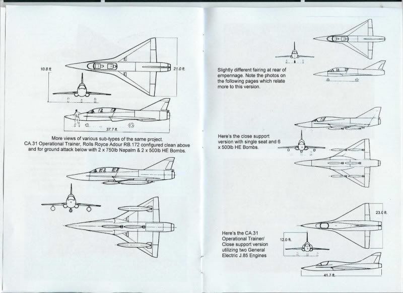
Said model kit may be found here: RAAF CA-31 1/72 model
[edit: fixed link to Secret Projects thread}
Bager1968Because NG pulled out well over a month ago, and EADS still wants the contract.
Do keep up.
Bager1968I did zoom in. While the gray area on the leading edge is clear, I couldn’t see any line indicating a split.
Bager1968After all, it was the Chinese who created the curse “May you live in interesting times:!
Bager1968If there will only be two carriers, why does the RN need six Type 45s? (And they wanted twelve initially.) I thought their job was to provide air defence for a carrier group.
2 CVF, 1 LPH (Ocean), 2 LPD (Albion, Bulwark), 4 “LPD-lite” (Bay class).
9 major ships, all needing AAW coverage, and not always operating together.
Bager1968That’s funny… I didn’t see one with the wings actually folded.
I agree it might be just the smallness of the image size that hides the split in the leading-edge slats… but we need either a better picture of the area in question or a picture of a J-15 with the wings folded to conclusively say one way or another.
Actually, a wing-fold really isn’t that hard to engineer, even a self-powered one… as long as the internal structure of the wing is designed to properly support the hinges and locking pins.
The question is simply “have they done it or not”, not “can they do it”.
Bager1968I heard about the lca in the ether.
you still believe in the existence of ether ? fascinating.
There must be an “ether”… my computer has an “ethernet connection”! 😀
Bager1968I’m wonder if LM would have to further strenghten the MLG if the F-35B/C are to operate out from ‘ski jump’ Carrier?
Thanks
The F-35B is already designed to take off using a “ski jump”… both British carriers being built will have them, and both the Italian Cavour and the Spanish Juan Carlos I have them… and all 4 ships are intended to operate the F-35B.
The F-35C is up for question here… its higher take-off weight might be a problem… no info has been released on whether it could use a “ski jump” or not.
Bager1968Yes, the hook is clear in that picture… as are the full-span leading-edge slats.
Which makes it very clear there is no folding wing on this aircraft, in contrast to the real Su-33.
It could be flown off ex-Varyag as a training aircraft, but it could not be taken down into the hangar without folding wings.
You can clearly see the break in the Su-33’s two-piece slats here:


Bager1968The plan the RN had for fitting Ikara on the Leanders was to provide “stand-off ASW” capability during conditions which would preclude Wasp/Lynx from operating (night/bad weather).
The zareba was to protect it from wave damage and ice formation in the north Atlantic (especially during winter) in its exposed bow position on HMS Bristol.
Part of the fragility was due to the RN Ikara launcher being more complex… to provide a reload time in seconds rather than minutes, and to launch that winged steerable-in-flight torpedo-dropping drone with minute precision.
The Leanders had far more wave problems, so the zareba really was needed with the launcher on the bow. Of course, the launcher was on the bow because it was so large that was the only place it could go.
Admitting it could be reduced in size and placed on the stern would have required admitting they had taken the wrong course with all that costly over-engineered design work… and you know that would never happen.
See the logic?
Down under, the RAN decided that taking a couple of minutes to reload was fine, and that aiming the launcher within a couple of degrees of the exact course to the target was acceptable, as the controller would then just twitch his steering controls a smidge and it would be on-course.
Therefore, the launcher could be small, which meant it could be placed on the stern, where it got very little wave action (and it could take the water better because it was simpler and less fragile).
The RAN also operated mainly in much warmer waters than the RN, with only the underbelly of the continent (the Great Australian Bight) being subject to icing conditions… and operating there would require hostile submarines to make a very long voyage around one end or the other, and for very little potential gain.
Bager1968The one in the Indian Ocean is there in case TLAMs need to be tossed into the Iraq/Iran/Afghanistan theater.
It will be patrolling off the western Pakistan coast and the Iranian coast.
Bager1968Smaller wing = faster roll-rate, greater G-rating, and better low altitude/rough air flight characteristics.
Better for A-A work, and for low-level A-G work.
Bager1968RAN Ikara installation; aft starboard side; HMAS Swan.
The Mk.10 Limbo launcher was later removed to provide a helo landing spot, but the extended superstructure for increased accommodation precluded a hangar.

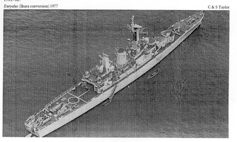
Here is the RN’s installation on the same basic design of hull, note the Ikara forward, the hangar & landing pad aft, then the Mk.10, then the VDS in the stern.
HMS Naiad F39 in 1982: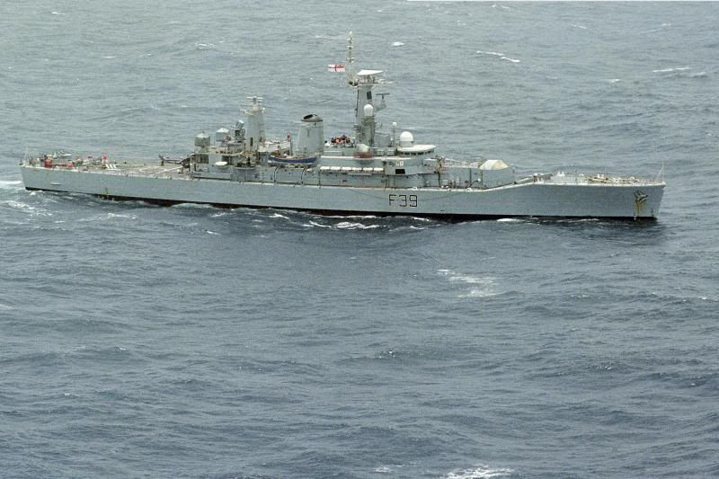
Bager1968Because they had escorted AF-1 in from Utah and either hadn’t landed of were on their way back out?
Because they were at Nellis for an exercise or training and just happened to be in the air at the time?
They didn’t and Nellis-based F-16s did, and the reporter screwed up his research?
Bager1968When they built the S-3 Viking.
On 4 August 1969, Lockheed’s design was selected as the winner of the contest, and eight prototypes, designated YS-3A were ordered. The first prototype flew on 21 January 1972 and the S-3 entered service in 1974. During the production run from 1974 to 1978, a total of 186 S-3As were built.
Last one built 1978, last carrier-based S-3 squadron stood down 29 January 2009.


 Sign In