Lancaster nose longeron kink
Yes, JT442. The 2nd photo illustrates it very well. Super photos by the way.
But in your photo it seems more of a curve rather than a kink with the apex of the curve well in front of frame F, almost at frame G.
Your photo is square on. So there is no distortion. It looks to me that your photo proves the kink/curve in the longeron. Agreed?
Many thanks
Mike
Mike, as you can see, a higher resolution image of the turret interior could be a considerable benefit. Yes please, I like a copy of the original. It’s very kind of you. My email is mikehoulder-at-yahoo.com As always replace -at-
Mike
Vertical Channel Supports
Geoff, I’ll do my very best.
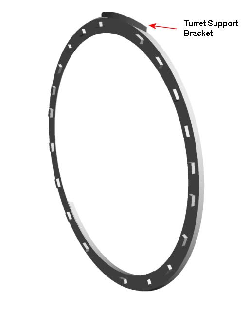
Which is it you want?
This
or this
If it’s the first, then more photos would help. I will have to calculate the dimensions using what I know of the turret bowl and the frames H & J
Mike
Brilliant Stuff!!!
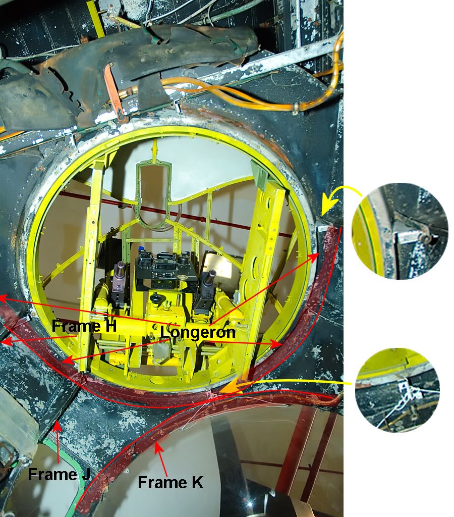
Thank you greatly Geoff. Your description gives a support sequence which runs like this:
Frame K -> Turret Support Bracket (Geoff’s angled plate) on top of K -> Vertical Channel Support -> Turret Bowl Angled Face -> Turret Deck and Longeron
The critical difference is that I was looking for a vertical channel support directly connecting the turret support bracket to the deck and/or longeron. But from your description the static and dynamic forces pass through the turret bowl between the longeron and frame K. That I never thought of. Brilliant.
In fact, this is shown in turretboy’s 3rd photo. I was very excited to see that photo, turretboy. I’ve been dreaming of getting one like that for ages.
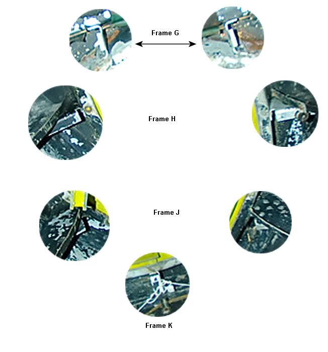
Here’s your photo again with some identification overlaid.
I presume that the two circular insets show Geoff’s Vertical Channel Supports. Is that correct, Geoff? There seems to be 7 of them in all. 2 on the channel beam stretching across frame G. 1 each for frames H, K either side and 1 at the nose.
In this game, of course, the answer to one question produces yet another question. At least 3 of the vertical channel supports seem to have a Philips head screw. Now what would that be for? I can’t believe the roll and pitch angles of the turret bowl and deck could be adjusted or could they? If so, the deck and bowl are independent of the longeron since that obviously cannot be adjusted.
One thing also that is very good. The gap between frame K and the longeron is much smaller than I have drawn. So that is one major error identified and to be eliminated
Thank you so much, all three of you
Mike
Reinforcing skin plates
“The hip bone is connected to the leg bone” etc etc
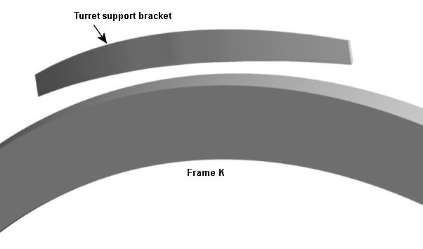
The turret ring rests on the turret deck. The turret deck is supported by the main longeron which, in turn, at the side s by frames J and H. The deck is supported at the rear by a channel bar stretching across frame G. But what about at the front?
Here’s frame K with the turret support bracket indicated (it’s called this in the Avro drawing). It looks as though it is intended to support the longeron at the front.
Unfortunately, the longeron, turret deck and ring are angled up at the front which leaves a most uncomfortable gap between this bracket and the longeron/turret ring and deck.
There must be some support to avoid instability. But what is it? I’m thinking it may be external reinforcing skin plates of the form I suggest in my drawing. You can just see something like this in my photo if you blow it up.
Mike
Mhuxt, I have a demo version of Rhino. I use it already for calculating moments of inertia. It looks to be a marvellous piece of software. Unfortunately, it involves a major change in work practice and I have not yet had the time to make the transition from my existing Cad system. At the moment I use a mesh modeller from Japan called Metasequoia.
Sometime soon I’ll have to make the transition!!
Mike
Let’s get the show on the road: Coordinate tables
Geoff, I can let you have tables for all the nose frames in a couple of days or so if you still want them after reading this.
That units in a Cad system are arbitrary is key. I could be working with something that is miles across in dimension or nanometres across. It makes no difference within the Cad system. It’s when the data has to come out of the Cad system into the real world that the problem starts. In the real world units matter and they cannot be arbitrary.
I can work happily within the Cad system drawing a Lancaster nose section frame, say J, to a precision of 1/10 of a mm (That’s more or less the standard Avro precision). But how do I get the info out into the world? The frames are symmetrical about the fuselage centre line. So I need only get out a half frame.
But frame J is one of the smallest frames. A full scale half J frame is still approx 632 x 1202 mm. It’s big and, for example, frame 1 is much bigger. Are there many printer/plotters accessible that can handle these sizes?
So I thought of a system of coordinate tables. For this, I take the raw data from the Cad system and work on it using MS Excel. I’ve sorted out the techniques necessary with the help of some good software. So I can proceed quite rapidly now.
A coordinate table is a set of X-Y coordinates which give the shape of one of the curves involved in one of the Lancaster frames/formers to full scale. The object is to plot these coordinates onto paper or wood to give a pattern for cutting the Alclad sheet to create a real frame.
For frame J, there are around 60 points to be plotted and I have tried to make it a bit easier by interpolating clean X values which are multiples of 20 mm. So X values range …,-40,-20,0,20,40,… about the fuselage centre line. The Y values are more complex, given to 1 decimal place.
Once the coordinates are plotted, the dots have to be joined by eye drawing the best curve possible through the plotted points.
OK, so what’s wrong. It’s not easy to plot the coordinates to such a large scale. Basically you have to draw first a very big piece of graph paper with, say, 5 cm squares. All the lines of the graph have to be parallel or perpendicular to a high degree of accuracy. That’s not easy. In fact, pretty difficult for most people. Once you have the graph paper arranged, it’s a lot easier. But arranging the graph paper is a major problem.
Neither printing on a printer/plotter nor the coordinate tables are a good solution. So how do I get my stuff out into the real world where it can be used by you guys?
I have attached an image of an Excel plot of frame J showing the curves which give the face of the frame and also the outer edges of the flanges which have to be bent down (4 curves). Also an image of the frame cross-section showing how the flanges should be bent downwards and a text coordinate table for the outer edge of the face for frame J.
Can anyone suggest a better method?
Mike
Geoff, you’re right. I’m up late
Geoff, I’ve been doing a pile of thinking since I read your last post.
One thing, I allowed myself to be confused over your identity; incredible stupidity on my part.
The main thing is that I must apologise very deeply for busting into your thread. I guess I am trying to find a community and it was that on my mind.
I admit it took me much more than ten hours as you guessed. We could have a fine old debate over our respective view points. But not now.
I want to say what I mean by the support I’m asking for. My nose section drawing looks pretty good, doesn’t it. But there are about a million things wrong or missing. I need your help, Geoff, to find and solve those errors and fix the bits that are missing. That’s one aspect of support.
The other aspect, what I do is in the computer and exists only for the moment. I hope to give a reality to what I do by helping you guys if I can find a way. Otherwise it is just like smoke.
My best wishes
Mike
Lancaster nose section formers and stringers
Hi folks, I am trying to produce CAD 3D drawings of the fuselage as precisely and as accurately as I can. Here’s a pic of my unfinished nose section:

I have a set of photocopies of Avro drawings for formers K, J, H, G, F on which I have done a reasonable job of deciphering illegible dimensions and correcting lens distortion.
If I can get formers E to 1 sorted out, I’m on a home run thereafter. Former E has the pilot’s instrument panel mounted on it and former 1 is the start of the navigator’s station. But unfortunately I have little or no information on formers E and 1 (as well as the intermediate cockpit frames D to A). I have the gross dimensions of former E as here:

I have three main problems at the moment and I would greatly welcome any help.
1. In side elevation the top four or five stringers between formers H and E form a flat deck in front of the windscreen leading down to front turret. That means that those stringers meet former E at an angle. My question: how is that angle managed? Is there a sharp bend to the horizontal at the end of those stringers to mate with E? Or is there a joining plate for each stringer to resolve the angle? Or something else? Stringers lower down don’t have this problem since they follow the plan view curve of the nose.
2. At the bottom of the structure between formers F and E on the port side, stringers 17 to 19 and the bottom longeron are omitted to give clearance for the F28 side and vertical camera ports. There appears to be a stringer separating the ports at about stringer station 20. To my mind, there is a serious structural weakness here as a consequence unless there is additional structure that I do not know about. Can anyone fill in this area for me?
3. Then, of course, the cockpit rail. The front elevation profiles of formers E and 1 are different from the top until they meet at a height below that of the top of the cockpit rail. There seem to me to be only three possibilities to take the rail from former 1 to former E which all cause problems for the canopy and opening window framework: the rail could be twisted some 10 degrees, the rail could be curved inwards in plan view, the rail could be inset into the cockpit area. I have drawings to illustrate this problem; bit I don’t want to overload this post. What is the solution?
Help, help please
Mike
This Argentine project looks to be very well founded with highly skilled people involved. I don’t know yet the level of restoration intended. But I would not be surprised if the aim is to fly the aircraft. I am particularly impressed with the 3d technical drawings that have been produced and I hope I can obtain some copies from them to show here. A project well worthy of support.
Blue_2: “Theakston’s, Black Sheep, Sam Smith’s” Oh such golden words. Next you’ll mention Almscliffe Crag of many happy memories and one really bad one.
Mike
Argie Lincoln Restoration
Is Yorkshire a different language? Well, the Spanish they speak in Argentina is different in about the same way. I’ve just made contact with the Argentine Avro Lincoln restoration group near Buenos Aires and offered any help I can. I’ve lived here in Argentina, an exile from Yorkshire, Tetleys and Baked Beans, for some 17 years now. I know quite a bit about the Lanc, but not the Lincoln. Perhaps the best I can offer them is to act as a sort of go-between, if they need it. But, please, give me some ideas how I can help them.
Mike
Some experimental numbers
I thought some numbers might be useful. Here is the model I am using for the initial experiments:

This is a very light and simple model aircraft with a wingspan of 120 cm and a total mass of 184 grms.
With all other joints set rigid, I concentrated on the left wing of the model. With selected spring and damping values which slowed the process down to make it visible, destructive resonance was seen. Resonance was restricted to left/right movement of the wing gradually increasing in amplitude to the point of breakage.
This occurred with a spring stiffness (Kf) of 3600 and a damping coeff (Df) of 1.06 on the Fuselage Left wing joint. The KF of 3600 might appear high; but it corresponds, I think, to a maximum structure limit of 4g on the model. With Df at 1.06, destructive resonance occurred during a flight where no control inputs were made. Increasing the Df to 1.07 eliminated resonance under these conditions. Destructive resonance continued to occur above this value if maximum rudder was held; but ceased with a Df of 1.10.
It is possible that the Df unit is 10 Newtons while the Kf unit is 1 Newton. The critical damping coefficient for Kf = 3600 is 51.55 Newtons for this model. Using a value of Df = 5.155 seems to be correct in the simulator. But this is using my existing too simple math model of the damped spring with the formula sqrt(4 . mass . Kf)
Does a critical damping coeff of 51.55 Newtons appear to be reasonably consistent with a spring stiffness of 3600 Newtons?
Anything particularly strange about these numbers?
Mike
Thanks, Tony. That was quick. I thought I could assume a simplification where the vibrations were not propagated. That they are propagated suggests that the simulator deserves respect.
My immediate objective is to get to good Kf and Df values. But there is another problem looming. Some one has mentioned the dreaded words ‘tensor analysis’ in the parametrisation of the inertia values. Know anything about that? I’m clueless.
Mike
Thanks very much indeed, Mark
Plan B
I’ve got to accept that it is now unlikely that the data I need still exists.
I believe it would be reasonably easy to calculate the volumes of the various structure components. Then if only I had a value of the individual structure density of these, I would have a reasonable approximation – I think?
Now if I assume that the individual structure component density across the major constructors of that time was more or less the same. I can apply those to the Lancaster to obtain an approximation to the individual weights – valid assumption?
So how do I get this information for aircraft like the B24 and the HP Halifax? Or has this gone with the wind as well?
Comments, criticism, help and brickbats – all gratefully received.
Mike


 Sign In