mhuxt, thanks for the thoughts. But it’s not quite so simple. I can’t expect any users to have a similar sophisticated CAD setup. So distribution in the original CAD format is not possible; even though at this stage the files have a reasonable size. They have to be distributed in a graphical file format. In .TIF format the photocopies I am using as an original source come out at about 16 Mb. To be able to embed the numbers legibly into the drawing this size will have to be scaled up significantly by some factor (i.e. in both dimensions) giving a horrendous file size just for one drawing. Using the most efficient .JPG format without compression rather than .TIF reduces the file size by a factor of about 2.5 . That is still way beyond my Internet bandwidth. And what about the user; can a file that size be opened? Remember this is not a commercial operation justifying on the part of the user the purchase of special computer equipment or software.
This note is very hurried and your replies deserve better from me. I’ll make a better reply later
Many thanks, mhuxt, and many thanks to you too, QldSpitty
Mike
A Problem of Representation
I have a problem for which as yet I cannot see a solution. Hopefully, writing about it will force the little grey cells to come up with a solution. And, maybe, some one else has already solved the problem and can advise me.
The project is not one for private enjoyment. My intention is to work at a level of detail and precision that might aid people who want to replicate parts of the Lancaster. I believe my data is in use by two separate projects of this nature.
The problem: if the data is to be used by others, how do I get the data to them in a usable form?
The first stage of the project is to create accurate 2D reconstructions of the original Avro engineering drawings. These drawings as they stand are distorted, damaged poor photocopies of the originals which, possibly, had already suffered fire damage. Thanks to advice already received in this forum, nearly 99% of my data is derived from the dimensions or numbers given and not from the drawings themselves which always were inaccurate by definition.
While the data is in my CAD system or my Excel spreadsheets, there is no problem. But that’s not usable by anyone else. No engineer I know of is going to do anything with a great slodge of, maybe, hundreds of thousands of numbers. There has to be a graphical base to make the numbers intelligible and usable. Here’s the problem. The original drawings were very large. Say A1 paper size. I can’t print monsters like that. I can’t even distribute drawings at this scale by Internet in paper-less form. So how do I get info that needs A1 onto an A4 (letter) paper size?
The system I used for simpler Lancaster components is only just about all right. Such as for the simpler formers/frames of the nose section, K, J, H. But now for the more complicated nose section formers G and F, the system blows up.
Here’s an unfinished representation of former/frame G:

How in the name of all that is Holy do I get the information contained in this image into a form usable by an engineer. I can include scrap 3D views which can explain things like this. First, how the top joint between the two halves of the former works:


And now, at the bottom of former G, how the former joins onto the intercostal which makes the side of the escape hatch:


To have these scrap views is helpful; but they do absolutely nothing for the important part: the location and relative location/position of the many details of the former shown above. If I had A1 size paper, I could do as the original draughtsmen did. I could put the numbers in good locations in the drawing of the former itself with explanatory arrows etc. With an A4 (letter) paper size, no way Jose!
I am forced to separate the numbers from the drawings with some sort of indexing system to relate them together. That I do not like. It’s ok for formers K,J,H. But it becomes intolerable with this former G.
That’s the problem. Any ideas, anyone?
Mike
LL12 as a wheel fragment
Mark, you gave the width of the face as 25 mm. Following Peter’s suggestion that LL12 might be a fragment of wheel, using the constructions shown in the attached pic, the wheel has estimated dimensions:
inner diameter 96 mm (3.8″)
outer diameter 146 mm (5.7″)
That’s not structural. My error.
What it might be is part of the engine or flying control linkages. Unfortunately my work has been limited to the nose section and I know very little beyond that.
If you do find parts of the nose structure, I will be over the moon.
Mike
Is ll12 a fragment of a wheel
That’s great lateral thinking, Peter. Here’s an image of a wheel superimposed. I have to leave now. I should be able to estimate the diameter of any such wheel.
I’ll post that when I return.
Mike
That’s pretty small. In fact, there’s nothing that small by way of structure in the nose section. The normal diameter for lightening holes in the nose section is 35 mm.
It is definitely a structural piece as it follows the Avro standard shape for these. But it comes from somewhere else in the aircraft.
Leave it with me. If I find it or change my mind, I’ll tell you.
Mike
Mark, I’m sorry. I meant LL12
Mike
http://i535.photobucket.com/albums/e…cparts/LL2.jpg looks very much like a piece of former or intercostal
What are the dimensions? Perhaps 2 3/4″ width across the face and 5/8″ depth of flange. If so, that would suggest that it is a piece of former.
On the other hand the lightening holes are closer together than I have seen yet on any former. Much more likely it is a piece of intercostal.
My best guess is a piece of intercostal supporting the sides of the escape hatch between formers F and H in the bomb aimer’s compartment.
I think the curvature is very pronounced. Intercostals in the area above had the greatest curvature; but maybe not so much as this fragment.
Mike
Many thanks
Many thanks, Planemike.
I’ve got those two now.
Mike
G-AJOD and G-ALCS
Hi, I wonder if anyone has photos of my father’s Messenger G-AJOD or his Gemini G-ALCS.
He is aged 95 years now and I think it would give him great pleasure to see his old aircraft.
Best to all
Mike
Wow! What a difference just using the numbers makes
Here are the numbers. Three of them were illegible in the Avro drawing. I’ve replaced them with the closest fit I could produce. The numbers are in inches.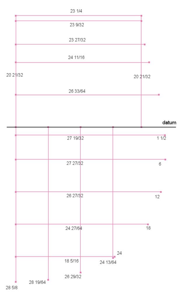
I produced the curve using a spline and a nice Interpolate function. I used some trig etc to produce the inner profile at the correct distance from the outer profile. Here is frame H superimposed on the Avro drawing: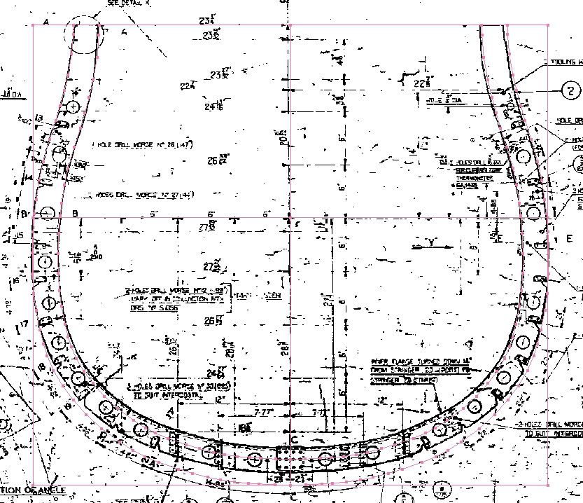
What a difference following just the numbers makes! I wouldn’t have dared depart so far from the Avro drawing without all your comments.
Mike
PS: It’s also solved the problem point 2 in my first post in this thread. Now the bottom of frame H meets the nose profile curve very nicely.
Yes, I remember the red faces when the video cable couldn’t reach the camera in the front of the fin when they were finishing the installation. But that’s not really the fault of CAD. CAD gives the possibility. It’s up to the designer to use it properly.
Mike
Very interesting replies
DavidS, am I correct? You say that there are significant differences in dimensions between individual Nimrod aircraft. Significant, not in operational terms, but in detailed draughting terms.That is, even today, a large complex design cannot be manufactured to a precision of less than some number of mm or cm. Wow! That blows my mind. For my own purposes, I can’t say yet whether that’s good or bad for my own work on the Lanc.
Also what this seems to say is that the jig construction was the most important part of the whole design process. That’s where you come in, aeronut 2008. It seems to me the jig engineers provided a reality check on the design office giving feedback through perhaps several iterations.
Who did the analysis that a particular small fastening, say, was not strong enough to carry its loads and that it needed to be beefed up? From the little I know, the design and stressing offices had insufficient manpower to do this sort of work. I can only believe it was the intuition and experience of the jig engineers that was responsible and who gave the necessary feedback to the design office.
My Lanc project is to understand the Lancaster as completely as I can. Everywhere I look there is an explosion of things to understand or techniques to learn. Now, here is a really major area completely new to me, the jig engineering of the Lanc. I feel this is probably the most important area of all and yet it seems there is a complete lack of documentation or history.
Mike
Us Yorkshiremen are far tighter than the Scots
Is that with an excess of Tetleys? Lucky people!
Lancaster weights = Shackleton weights approx
I’ve been trying fruitlessly for nine months now to find similar information for the structural weights of the Lancaster.
I think probably those of the Shack will be close enough for me. My intention is to calculate the moments of inertia for the major components. I have the volume of these from my own drawings. I need only the structure weights.
Also the weight of the propeller and undercarriage are important for me.
Can any of you help?
Mike
That’s great. The dreaded gap at the nose was giving me a lot of grief. I’ll redraw the nose section and send you a copy.
The only things I can suggest for the headache:
1. A pint of Tetleys (I owe you that). You being in Canada, it’ll have to be a virtual pint.
2. My horse Tornado lives underneath my study. So I would go for a cross-country blast on him. But that might have to be virtual as well.
Mike


 Sign In