powerandpassion
Bless you kind sir.
Mike
Cherry Ripe
Is this quote referring to the Lancaster?
This framework is covered with alclad (a light aluminium alloy) sheet, the majority being 22 SWG but in some places 16 SWG. This is riveted to the formers and stringers with dome-head rivets.
If so, I wonder if you can give the source.
Many thanks
Mike
It was a very attractive aeroplane with that turret stuck on front. I wish I had made a model of it.
Mike
‘Flight of the Phoenix’. Many thanks, you’ve got my query right. I like your image in underpants with 3 hours to produce a Lanc. But really all that sweat etc is not for me. I’m the DO, the seat polishers.
Mike
Asking the impossible – but why not!
Former E of the Lancaster sits between the nose section and the front centre section. While there are some other parts, the former is in two sections, both closed hoops joined top & bottom with short angle & channel parts. The front hoop is an angle section and is part of the nose. The rear hoop is an extruded channel section and is part of the front centre section. The two hoops are bolted together to join the nose & front centre sections together.
A good mate of mine wants to build this former but is in fearful trouble over the extruded channel. As he works the ally channel into shape, it becomes brittle and breaks.
Could this be avoided by a special ally alloy?
Unfortunately the original Avro drawings for the extruded channel itself are no longer on Earth. But I do have an Avro component drawing which suggests the material is SS.3075.
If this is the material code and a modern equivalent exists without costing the earth, then perhaps we are ok.
Is there the slightest chance you or anyone can help us with this.
Which top shelf brand do you like the best?
All the best
Mike
A good read, thanks
John, Tubby invited myself & my father to visit the set at Duxford, We arrived just after a minute’s silence had been called to honour a pilot who had been killed in an earlier accident in a Me109. I also remember a Me109 on jacks looking badly twisted after a ground loop. The problem is that my memory of that visit now has become very vague. How long were you at Elstree? Do you remember Tom Kilcoyne who rescued me several times? God bless him.
Mike
I called that spring weedy not just because the wire diameter is thin, but also because the coil geometry is not uniform.
It looks like a spring from a discarded mechanical toy which has been squeezed, stretched and bent.
I assume that aero engine valve springs are high precision items with near perfect geometries (Is that so?)
Completely dependent on intuition, my feeling is that geometric non-uniformity produces discontinuity in the force/strength values along the length of the wire.
These discontinuities produce weak points in the spring where perhaps fatigue resistance is greatly reduced.
Hence the pawl spring shown might have a much shorter useful life relative to your Merlin valve springs.
Of course, all this is a distraction from completing the planned work on the Browning and further delays the return to work on the Lancaster (which is where I want to be).
Mike
Who is Olivier21? Is he the owner of the photo?
Mike
Yes, a swiss watch and cycling more than 19 times a second.
Here’s a description of the action of the Feed mechanism from AP1641C:
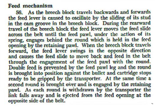
I’ve found two photos (from Walter’s collection) showing the underneath of the breech cover.
Here: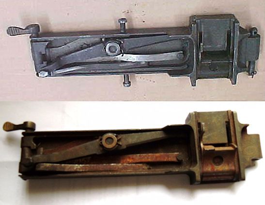
You can see the feed lever diagonally bottom left to top right.
The cam grooves are in the breech block itself (see below) into which the knob on the left end of the lever fits.
The feed slide moves within the housing to the right.
The right hand end of the lever goes through a slot in the housing, connects with the feed slide and waggles it up and down (as oriented to the photos)
In both cases the slide is shown at the top of its travel.
This corresponds to a new round having been pushed onto the gun centre line against the two stops which I have already drawn and shown in earlier posts.
To pick up a new round the slides would drop down pushed by the end of the feed lever as it rotates to the bottom right position.
The good news from these photos is that the feed pawl has no teeth.
The crucial bit: changing feed direction from left to right of the gun
The pawl slide is ok. Its leg or hook is bolted on and can be on the other side with the slide itself rotated 180 degrees.
But what about the feed lever and cam grooves in the top of the breech block!
Let’s look at the breech block cam grooves and the action on the feed lever with these drawings which come from AP1224 sheets 1 & 2.
In the drawings the breech block is bright silver and the feed lever in green.
For the breech cover photos above we were looking up.
For these two Ap1224 drawings we are looking down.
So the top AP1224 drawing is the one that corresponds to the breech cover photos with the breech fully forward and a round on the centre line of the gun. The feed is from the left of the gun.
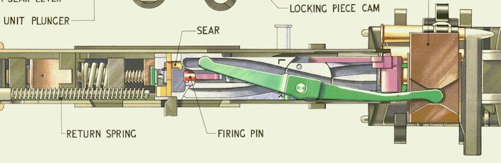
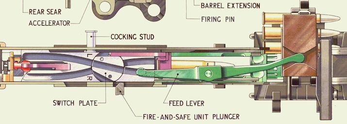
With the bottom AP1224, the breech block has gone to the back of the gun.
The knob on the feed lever has followed the groove through the turntable and has pushed the feed slide to its topmost position ready to pick the round waiting and held by the retaining pawl (see earlier posts)
There are two grooves with a steam engine turntable in the middle. One of the grooves is for a feed from the left & one from the right.
If the feed lever pivot was on the centre line and without the kinks shown on the right hand arm, just changing the turntable and using the second groove could not do the job of changing to a feed from the right. A new feed lever would necessary.
I think that’s avoided cleverly by offsetting the lever pivot and kinking the arm of the lever. But I need to prove that.
Oh wow! my head is spinning. At least there are no teeth to draw.
Mike
LHS & RHS feed for RAF gun
The RAF Browning .303 MkII has its feed base changed from left hand to right hand relatively easily as I’ve shown above.
I’ve been lucky enough to make contact with Charlie Brown in the States.
He has given me a set of engineering drawings sufficient for those internal components I intend to draw.
The main difference as far as I can see, to the level I intend to work, is that the US gun is made for a feed only from the left of the gun.
So, to draw the RAF gun I have to modify related components from the US drawings using photos of the equivalent RAF ones.
So far, I have found four more items which have to be changed to allow a bi-directional feed. These are:
Feed lever (belt feed lever US)
Feed slide (belt feed slide US)
Feed pawl (belt feed pawl US)
Breech block (bolt US) (RAF breech block has two channels symmetric about the centre line instead of one to work the feed lever in opposite senses)
It is the feed pawl which is causing me problems at the moment. Here it is at a very early stage.
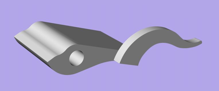
The US drawing has the leg of the pawl welded to the barrel of the pawl (as shown)
Simply rotating the feed pawl by 180 degrees would cause the pawl hook or leg to engage a thinner part of the cartridge,
So this simple solution cannot serve.
The photo in RAF AP1641C shows the leg as a separate part to the barrel (pawl) which can be fitted either side of the pawl barrel using a pin.
So solving the problem.
Unfortunately the AP1641C photo is far too small to show any detail.
I wonder if any kind person has a photo of the RAF feed pawl showing the design of the leg or hook that they can give me.
The US version has three rows each of eleven teeth on the end of the barrel in order to grip the cartridge more securely.
It would be nice to know if the RAF version also had these teeth.
It would be nice to know if I could omit them as they are going to be a B*** to draw.
Mike
Yes, ok. But what about Lancaster frame E. In two parts, a L section which would be relatively easy. But what about the extrusion part with an open rectangular section. That’s really nasty.
Mike
And next ….
There is some help for the following in Walter’s collection and I have found some more in Internet.
Bu I need more, much more, info & component shapes.
Here’s the list of items as it stands today:
Transporter(Br)/Extractor(US)
Transporter
Transporter plunger
Transporter claw
Transporter stop
Front transporter cam
Rear transporter cam
Breech Cover
Breech cover catch
Breech cover catch axis pin with lever
Breech cover catch spring
Treansporter guide spring
Transporter ramp
Feed lever
Feed lever plunger with spring
Feed lever bush and split pin
Feed lever stud
Feed slide
Feed pawl
Feed pawl pin with retainer
Feed pawl leg
Feed pawl leg pin
Feed pawl spring
Then all the bits for the following assemblies
Breech Block
Lock Frame
Barrel Extension
Some of the items can be skipped e.g. pins & springs, but there’s a great many parts to draw
Any help will be greatly appreciated.
Mike
Help, please
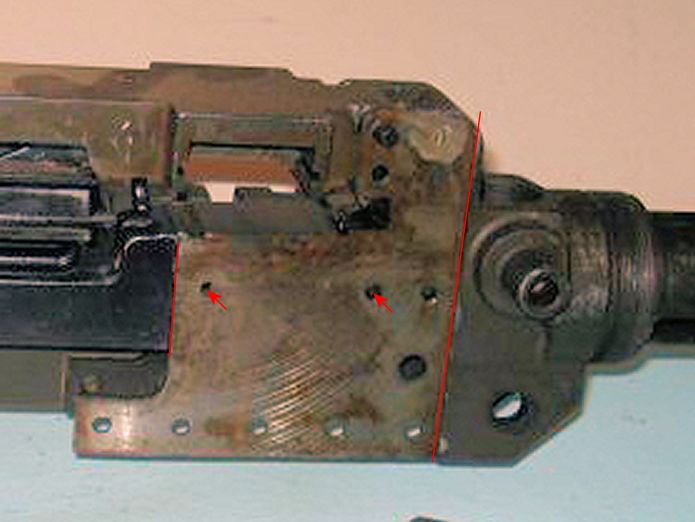
In my work on the trunnion and ammunition feed area I have ommited the 3/32″ skin plate which fills the gap between the trunnion and the side bars. But I can’t for the life of me see how the side bars were fixed to either the trunnion itself or to the missing skin plate.
Can anyone help on this question? All these images come from Walter’s collection.
Here someone has stripped off both the side bar itself and the skin plate. The plate would lie between the two vertical lines. There are only two rivet holes which could possibly relate to the side bars. These are shown with arrows.
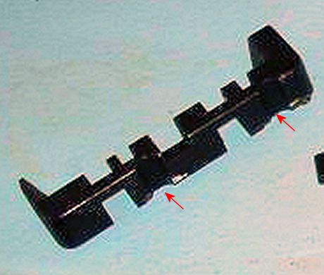
Unfortunately, the following image of the side bar shows that while there is clearance for those two rivets, shown by arrows, there is no internal flange which could join the side bar to either the skin plate or the trunnion. These two images are sections from the same photo.
[
Now looking at the top of the trunnion and side bar, the joints between the trunnion, skin plate & side bar are fine, almost as though they were welded and ground flat. The red lines are witnesses to the joints. The inner line is the joint between the trunnion & the skin plate; the outer between the side bar & the skin plate.

Here is the same image without the witness lines.
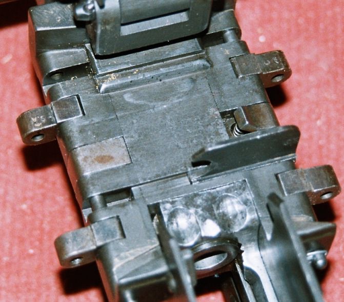
A further thought, if the two rivets indicated in the first image did join the side bar to the skin plate & trunnion, would such a fine joint bwteen them be possible. My argument being that the two rivets lie at the bottom of the side bar and as a result the free join at the top of the side bar could not be as fine as shown in the photo.
Comments are very welcome. This has peeved me for some time.
Mike
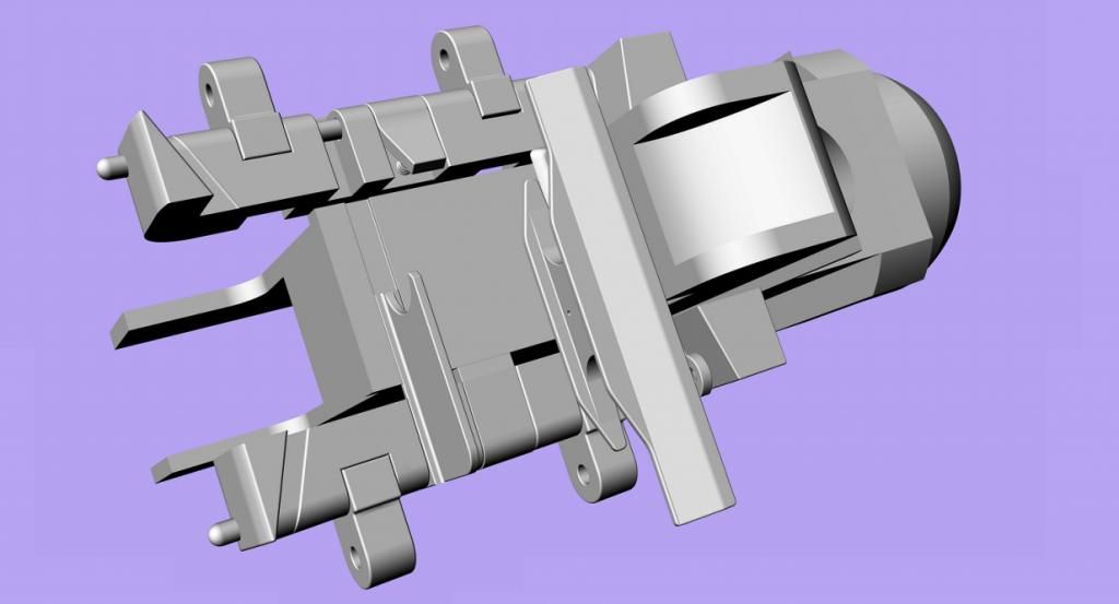
Front Cartridge Stop
Here are my main sources for the front cartridge stop (thanks to Walter)
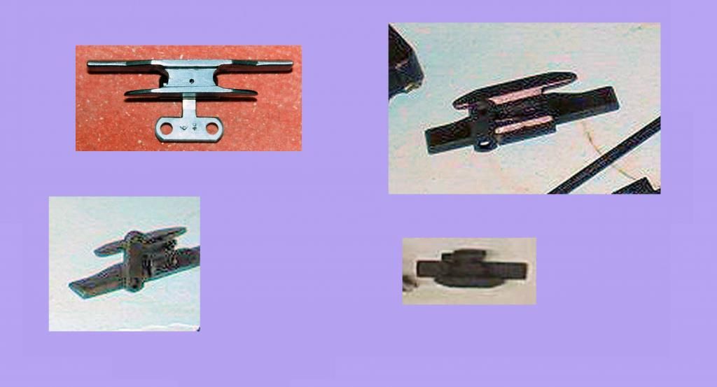
Other views of the whole or parts of the gun show the rear of the front stop but the front of the stop is not visible. It has been difficult to determine the configuration of the front of the stop even from these sources. My estimate is that these four photos show three different versions. I’ve studied them until my eyes popped out. Shall we say that my rendering of the front of the stop uses intelligent guess work.
Here’s the trunnion, the side bars & other bits together with the finished front stop in its location.
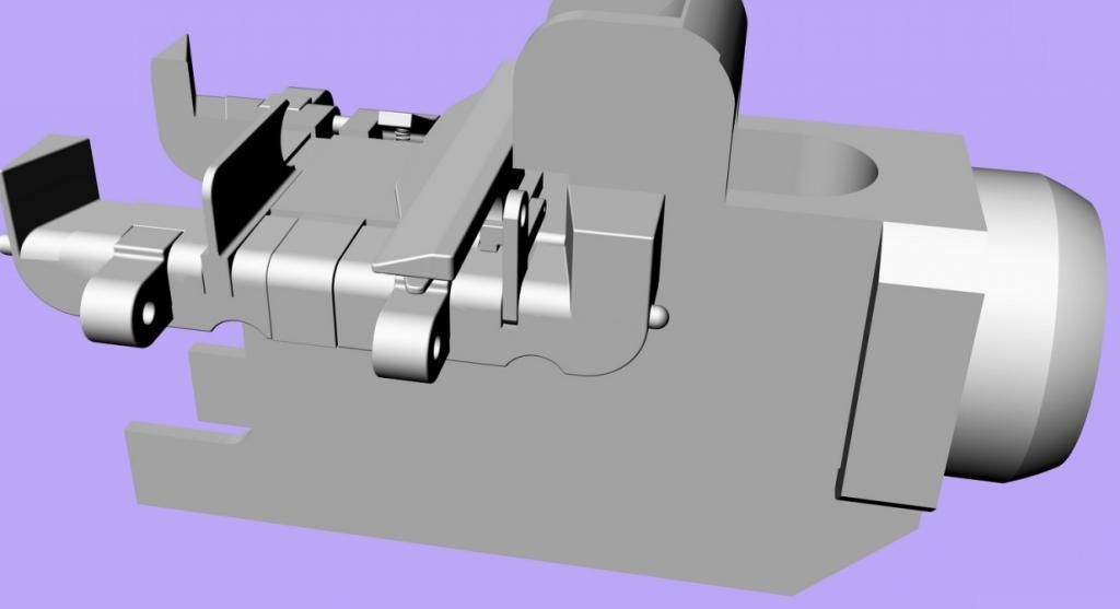
This shows how the front stop is locked in position using the T bracket locked to the pin passing through the side bars and a key way which is in fact part of the trunnion.
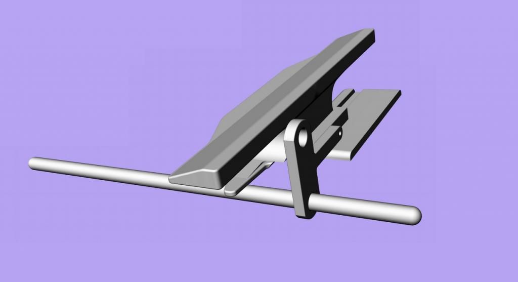
These are two views of the front stop, T bracket and trunnion key way.
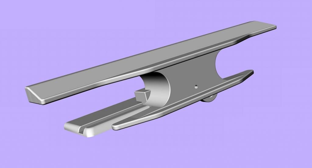
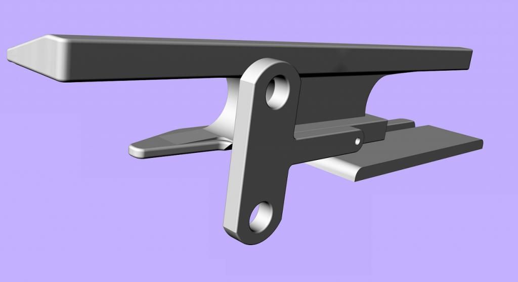
This show how the stop works. The incoming round is held in the centre position by the stop allowing the transport of the round backwards & downwards into the breech of the barrel.
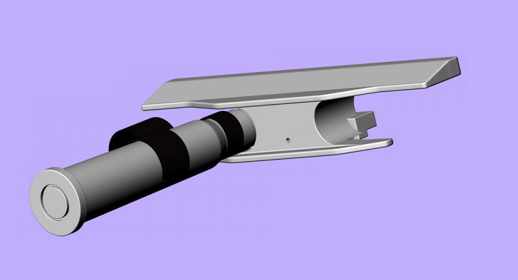
The reason for this complication is to allow the ammunition belt feed to come from the left or the right of the gun. Release the side bar locking pin. Swivel the T bracket 180 degrees and slide the stop over to the other side. At the same time, change over the retaining pawl and filling piece and re-position the rear stop. With experienced fingers, it could be done in the time it took to type this description or less.
This shows the parts arranged for a feed from the left of the gun.
The happiest of new years to all
Mike


 Sign In