To paraphrase the reported words of, I think, a wing commander just arrived on an operational squadron from a long spell of instructing. When someone asked what he would be doing at Christmas with his children, he replied “Oh, I won’t be here” and he wasn’t.
That is in one of my innumerable Bomber Command biographical books. But which one? I can’t say.
The point is that the protecting mantra “it will be the other bloke” probably had a very limited currency. Harris said something along the lines of “the bravery of the small hours of the night”. Then there’s the title of fighter pilot Brian Kingcome’s book “A willingness to die”. He becomes dimly aware of this concept early on operations and refines it as his experience develops. I’m sure analogies of this concept were widespread in Bomber Command.
I’ve tried to visualise myself so many times in their situation. I’m sure I would not have had their courage to face consciously an excruciating death on every op. I think it would have been LMF for me.
Mike
Pretty illegible at this size. Is it possible to post full size images of these signatures?
Mike
I think this Browning Mk II is the one fitted to Spits & Hurricanes.
It needs the blast tube adapter instead of a cover for the adapter thread.
Somewhere very recently I’ve seen a Browning installation in a Spitfire/Hurricane, possibly here, but I can’t remember where it was. Perhaps some one can show us where.
The gun was without the flash eliminator but had, I believe, the muzzle attachment choke.
Also it seemed to have two chutes one for links and the other an ammunition feed chute.
Mike
Since my last post, I have been given much better, much larger, much clearer copies of AP 1224 sheets 1 & 2.
This has meant that I have a better idea of the spacing & size of the cutouts in the side bars. I must send you a copy, Walter.
In addition, I have been improving my techniques particularly with filleted edges of solid shapes. I feel that with the reflection of light on these edges the parts come to life in a big way. Of, course, thrilled with this effect, I may have over-done it.
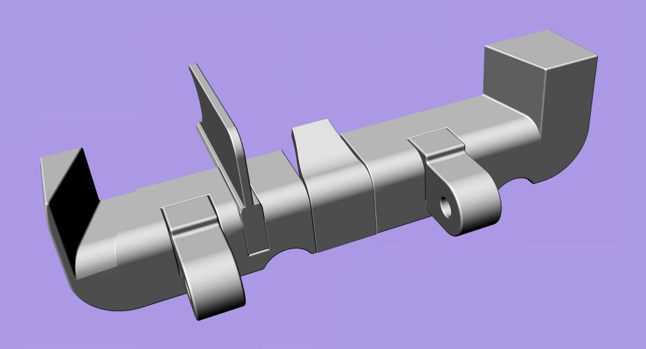
Here is the side bar re-done with the aid of the new AP 1224’s. Its dimensions now are very close to the prototype. I can’t say exact as I do not have the engineering drawings.
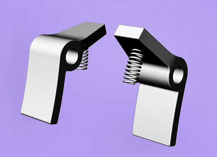
Here is the new retaining pawl. Its tail is substantially longer and is curved as well.
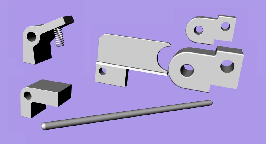
Here are two views of nearly all the parts required at this stage. The front cartridge stop is shown but it requires quite a bit of work still as well as the swiveling bracket whose groove is now shown. This bracket is used to lock the front stop in place.
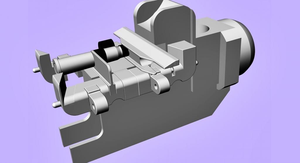
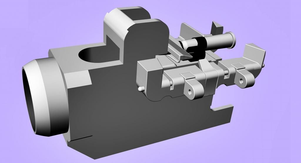
Mike
This is nothing to do with the crash. But “Pretty pretty please with cherries on top” I loved. Thank you Ana.
Mike
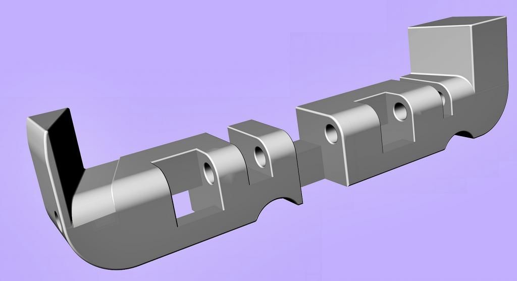
Side bars in progress
This shows the starboard bar without its components. A groove for the swiveling bracket of the front cartridge stop still needs to be added.
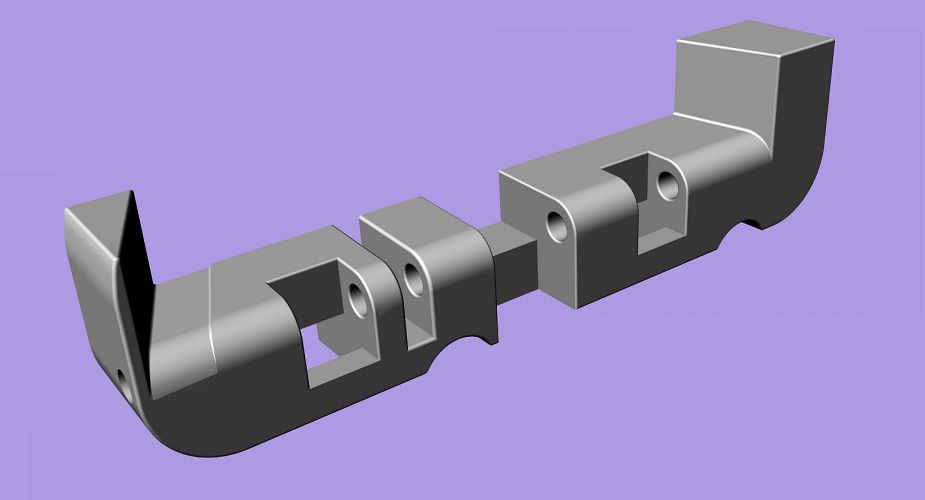
This shows the bar with its components. There is still work to be done on the retaining pawl. The pawl is shown on the same side as the rear cartridge stop for convenience. It should be on the opposite bar.
The interior view
This shows the filling piece which goes on same side as the rear cartridge stop
Clockwise from the top left, this shows the components:
retaing pawl
rear cartridge stop
two ammunition box lugs
locking pin without wire safeties
filling piece
mike
Side bars in progress

Started side bars. They will help to determine the front part of the cartridge stop.
Mike
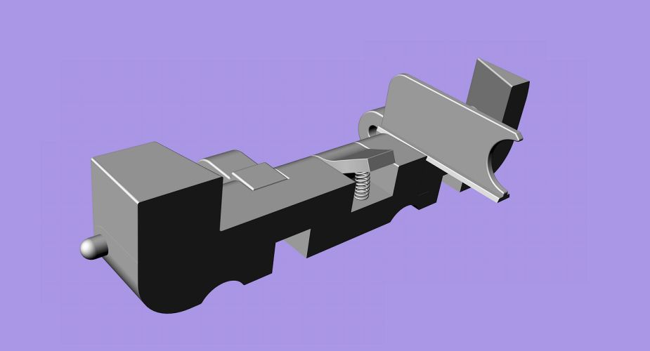
Front cartridge stop in progress
Here’s the front cartridge stop in progress. Bluntly it has been a nightmare.
There is no way I can claim precision to the original. Mine does no more than suggest functionality.
The work has advanced considerably my techniques, particularly with two dimensional fillets.
But I did not have the courage to tackle tapering the inner edges of the wings to their ends in rear elevation.
The forward elevation which will show the swiveling T bracket will be no more than intelligent guess work when it’s done.
Mike


I don’t have or can’t find 5/R2103. But I do have Avro drawings
7/R2103 Distance Tube
8/R2103 Chain retaining block Aileron control sprocket behind rear spar.
9/R2103 Rubbing plate: Aileron control sprockets behind rear spar
11/R2103 Rubbing plate: Aileron control sprockets behind rear spar
“Behind rear spar” suggests perhaps that the part was in the wing attached to the ailerons, not in the Front Centre Section
Mike
Powerful stuff and very well expressed, powerandpassion.
Unfortunately I find none of your explanations/excuses express the truth, at least for me.
How do I go from drawing disintegrating RAF .303 belt clips with a nice rack of rounds to recite Vespers?
Understanding the technology of the Lancaster is a very big thrill. But how do I divorce myself from the consequences? And then pray “Lord, show your love to all men”.
Why is it weapons that provide the thrill of understanding, the lust to understand and possess the understanding? Ploughshares are boring. Yes, a DH Comet 4 is beautiful, but I’d go for a Lanc, Halifax or Stirling any time. Not so much a Wellington, funnily enough.
Or is it simply that I was born in the middle of WWII, surrounded by uniforms, big powerful military machinery and people living at a different level of intensity?
Mike
Front cartridge & bullet nose stop
I’ve been having some trouble understanding these. I can see some light now, but will need a day or too to produce drawings that explain the thing. So here is the complete stock of images and photos I have had to work on the problem. Most, if not all, come from Walter for which many thanks.
No 1. shows the front cartridge stop. My head ached to see which part of this was the bullet nose stop. I have finally come to the conclusion that they are separate parts. See images 8 and 9 below.

No 2. This is an image from AP 1641 C which discusses the RAF Browning in detail. This image shows how the T bracket swivels. While there may be also a key slot, this bracket, swiveling to either side, fixes the cartridge stop to the trunnion via one of the retaining pawl pins. See image 4 below,

No. 3. This shows the front cartridge stop in position on the trunnion bed. Using the swiveling T bracket, it can be placed to either side depending whether the ammunition feed is on the left or the right. In this photo, judging by the active retaining pawl and the rear cartridge stop, the front stop is on the wrong side. I’ll explain why I believe this to be so with drawings in a couple of days.

No. 4. This show how the swiveling T bracket locks onto one of the retaining pawl pins.

No. 5, 6, 7. I have to try to determine the plan and side elevations of the front cartridge stop from this and the following two images.


No. 8. I’ve used this section from AD 1224/2 to determine the overall proportions of the front cartridge stop and the the bullet nose stop. I agonised for hours trying to find a way in which both these two could be part of the same component.

No. 9. I extracted these line drawings from AD 1224/2. For me, taking account of Nos 5,6,7 above, it is clear that the front cartridge stop & the bullet nose stop are separate components.

I need to make my case with aid of some drawings in the next couple of days.
Mike
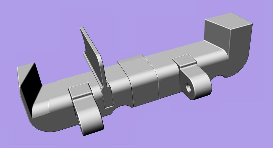
Back at work after the hols(????)
Here’s what the gun looks like now.

I have to get the feed sorted out next.
Mike
Facflaggie, different parts of the skin had different thicknesses and spacing between rivets differed.
But as an indication, the skin of the nose section, according to my Avro drawings, was 1/32″ thickness.
As a yardstick for rivet spacing, many were about 1″ apart.
Of course, formers and other components had many different gauges.
Hope that helps.
Mike
Peter, you always have stunning photos. Thank you. Mike
Please forgive me butting in.
I like very much to see something of the Schrage Musik installation in the 110 and, perhaps, the gun sight used.
There may have been a previous thread that did this. If so, I’d be grateful for some indication of its location.
Best wishes
Mike


 Sign In