Thanks
Yes, it does help, Smirky. Thank you very much.
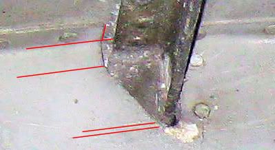
The formers in your photo seem to come from the centre or the rear centre section of the Lanc. All formers in these two regions, except transport joints, are made with either 18 gauge (1.024 mm) or 10 gauge (2.588 mm) Alclad sheet. The former nearest the camera is 18 gauge; the next is 10 gauge, the third is either 18 or 10 gauge. I’m not sure of the last.
All three formers are facing the same way. That should have been enough to identify the formers 100%. The best I can do is to identify them probably as formers 23, 22, 21 looking to the front. Do you know better?
Here are some pics to show you what I am doing to extract the data I need:
A section from a Lancaster engineering drawing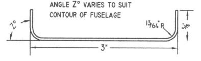
A framework to apply known dimensions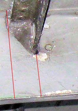
Angle Z in this case is 90 degrees. I need to think a bit more before deriving the numbers – tomorrow’s job.
Best wishes
Mike
Sources for Lancaster airframe jigs
This is fascinating stuff. I particularly like the stuff on interchangeability of components. The thought that RR ‘erected’ merlins using individually selected components is a bit of a shocker.
But my main interest for which I have found nothing as yet is the design and construction of airframe jigs particularly for the Lanc. Is it too late now or can anyone suggest any sources?
Mike
Please advise on holes necessary for MDF sandwich
Hi folks, here are the port & starboard MDF blanks for the sandwich to create the flanges on former/frame G. They are shown overlapping at the top centre joint. I have maximised the size of the drawing by turning it 90 degrees to the left. The top joint is at the left. I apologise for the size. But you would not see some of the holes in a smaller drawing.
The meat in the sandwich, the aluminium blank, will have all the holes shown plus a large number of smaller rivet holes marked. (I’ll have another question about these later). All the larger holes will have discs of aluminium inserted in the aluminium blank and screwed down in the sandwich. I understand that this is to prevent lateral distortion of the ali blank holes during the fashioning of the flanges which will cause some lateral stretching of the ali blank.
My question: do the smaller holes (0.14, 0.19, 0.31) need to be screwed right through the sandwich? i.e. Do the holes need to be made in the MDF blanks as well as the ali?

I have put them in up till now as some of the smaller holes are close to the inside edge and I am a bit nervous that, without them, there is a big unsupported gap in the top half of the MDF blanks.
Many thanks, folks.
Mike
You’re right, turretboy
Yes, Mike. It’s a sweep of the former cross-section closed curve along one of the edges of the former. The software is Rhino 4.
I’m sure it could be better; I’m right at the start of the learning curve for the new software.
Mike
First stumbling steps in new software
Just to show how nicely and precisely the new software copes with compound 3D curves. The radiused corners of the former were a nightmare in the old software.
Mike


Many, many thanks, Firebex. If you’re ever in Argentina …. All I can do otherwise is send you a virtual pint of Tetleys. I wish the world was a bit smaller.
Mike
Lightening Holes Diameters
Sorry, Beermat, the Lanc nose section formers have lightening holes of finished diameter 1 3/8″ (34.93 mm). Much smaller than yours. But I think we both going to have to follow Firebex’s advice.
All the best
Mike
Sources for tools
Hi all. First, I’ve never got my hands dirty in my life. And as I am so far away from the action, it is most unlikely that I ever will. I suppose I am a one man drawing office doing my best to help two Lancaster part-replica projects. But I can’t ignore the cost and availability of tools etc.
I had a very quick look at the de Havilland Moth Club Service Register. Apart from one mention of tools for hire which needs to be explored, there doesn’t appear to be anything to fit the needs of the men doing this work. Two of the tools on the agenda at the moment are a die for drawing the stringers and some sort of reamer for making raised rims in the lightening holes of the formers. The issue for the first is cost, for the second finding the right size.
So therefore I would certainly support Firebex’s suggestion.
Best to all
Mike
RAF Browning .303 plans
Would you like a copy of my drawings/plans? The drawings were used by Jaime of Arizona Models to 3D print resin versions very successfully. Here are some views.


Please PM me if you are interested.
Mike
QldSpitty, please could you answer some practical questions arising from your post “This could take a while…” 1st May.
‘bend allowance’: Is this just the arc length of the radiused bend? Or does it allow for stretch in the Ali?
‘square off all corners from the flange foldline out to cutline’: Now why should you do that?
‘rivet hole centres added’: Does the waterjet just mark the rivet locations? Or does it actually drill them?
‘straighten with stretchers/shrinkers’: I recognise the need; but I have no concept or mental image of these tools.
Very many thanks
Mike
Use of the drawings
Thanks, OneEighthBit, for your ideas. As a means for building a business plan for justifying investment, I will certainly consider them very well.
I’ve a tiny bit of experience of 3D printing. I drew up a .303 Browning for a mate which was then printed by Jamie at http://www.arizonamodels.com at 1:9 scale.

Mike
RE-learn, Bloodnok. You must be joking. I was a maths and computer freak, not a real engineer. I feel enormously chuffed. I’ve hit the mother-load for which I’ve been looking for some two years. This sort of work is worth nothing without criticism from the experts.
As for what you’ve given me, QldSpitty. I’m overwhelmed.
Give me a little time to digest all this and I’ll be back, hopefully with some sensible comments.
Mike
Sorry Fouga23, I don’t understand fully what you say. Could you explain, please, in more detail?
Mike
Needs Must
Firebird, I’m sure you are right. I have certainly shared your desire in the past to see professionalism in software and related industries instead of what might be described as shambling amateurism. But look at the thing as it is. The field of Avro Lancaster replicas is not now sufficiently profitable to justify significant investment. I would love to have a copy of Catia; but only if I had a business plan to support it. Most of us in this area are now retired and do not have the physical energy to create new business opportunities. Also I certainly started with the very firm conviction that there is no essential difference between 3D visualisation and manufacturing data and they are just two different manifestations of the same thing. If I succeed, I’m right; otherwise I’m shot down in flames.
Now to move onto other aspects. One of the two users of my data is a professional engineer with a fully equipped workshop and clearly has more than sufficient experience of turning ideas into metal. I on the other hand am totally innocent of the relevant exigencies. Before my retirement, I was a software engineer at Texas Instruments spending most of my life with computers both theoretically and practically. So you could say that reality is always virtual for me. But the idea of providing the data in a format suitable for the cutting of former/frame blanks from Alclad 20 gauge by laser did occur to me.
My engineer friend strongly dissuaded me of this. The formers/frames have flanges at complicated angles to and radiused joints with the faces. Forgive my terminology; it was thought nearly impossible to cold-draw the flanges from the former blanks without cracking them. The only option was thought to be a process of heating and annealing using wooden masters to produce the desired shape. So the first part of my job is to provide data to enable wooden masters to be created.
The second part of my job is to ensure that all individual components fit together correctly. The most critical area in this respect is the fit of the stringers to the formers/frames. I’m hoping that the completed formers can be jigged accurately enough to allow the stringers to give the correct curves and lie correctly. But it is extremely important that I give the location of the stringer slots or cut-outs in the formers correctly.
The third part of my job is to give the position correctly of the various holes that are used to mount the various items of equipment. Perhaps this is not so critical as the equipment itself determines the position of the mounting holes. But I can’t be too far out.
The fourth part of my job is to understand the structure as well as I can and to provide a 3D visualisation as complete and as accurate as I can manage. This was my original intention and my starting objective.
My best to all
Mike
Software in use
I am using three different editors using the Max 3DS format to transit between them. They are
Mesh editors: AC3D (UK) and Metasequoia (Japan)
NURBS editor: Rhinoceros (USA)
NURBS are basically Bezier curves in 3 dimensions.
Mesh is a collection of points joined by straight lines which form a surface out of triangles and/or quadrilaterals
My favourite for day to day work is Metasequoia. I find it becomes deeper and deeper with use. Ultimately, Rhinoceros is by far the most powerful and, sadly, also the most expensive.


 Sign In