A deeper analysis of the problem
This is a problem of an inconsistent geometry with the forward support struts to the head armour plate on the pilot’s seat of the Lancaster. It is beginning to look to be an interesting problem and is worth a closer examination. I am not an engineer myself. I just like drawing and, of course, the Lanc. But I always invite Geoff to go through my work and rely on his guidance and comments.
Here is the pilot’s seat I have drawn. It is very nearly complete. All individual components have been drawn using Avro source material. Each component is in fact a separate drawing and, relatively easily, can be projected onto the standard 2D views with its dimensions. I have omitted rivet holes as they, particularly, are very expensive in computer memory requirements. They can be added for individual components at a later stage if required. As regards the seat, I have omitted also the Bowden cable connecting the harness release control to the harness release itself. I have not the skill to draw such a cable in a natural form. A couple of other non-visible items are omitted such as the harness release pin itself and the long harness release spring enclosed within the spring tube. I have taken liberties with various nuts & bolts.
Here is a closer view of the problem area. It shows the top area of the seat with the central harness release and the elevator gust locking bar socket. At the sides are the forward bottom lugs to hold the bottom ends of the strut sockets. Above is the head armour plate with its support struts.
Here is the problem itself. The location of the top parts of the support struts are inconsistent with the location of the bottom parts of those struts. The struts are shown vertical in front view in Avro N.829. But then the sockets at the bottom of the struts do not engage with the corresponding lug on the seat top plate.
Here are measurements of my drawing of these items. The top dimension has been rounded down 1/64” by the system and should read 17 3/8”, not 17 23/64”. It’s that 3/8” that is the problem.
Taking dimensions directly from Avro drawings, we have 17″ between bottom strut centre lines and 16 + 2*(11/16) + 2*(0.05) = 17.475 ” between top strut centre lines.
The sources for my measurements are:
The 17″ comes directly from 13/N.771 (dist between horn centres of seat top plate)
The 16″ comes directly from 2/N.796 (width of head armour plate)
11/16″ is a simple calculation from 4/N.796 (tube C/L to inner face of top socket, 15/16 – half tube width)
0.05 comes directly from 18/N.796 (special washer between inner face of strut top socket and edge of head armour plate/top lug)
This demonstrates as much as I am capable that the inconsistency is a real anomaly of the Avro engineering drawings.
Ok, so what to about this. Three possibilities.
Here are some critical dimensions of the strut comprising a tube, two forged sockets either end of the tube and the two lugs to mate with the sockets.
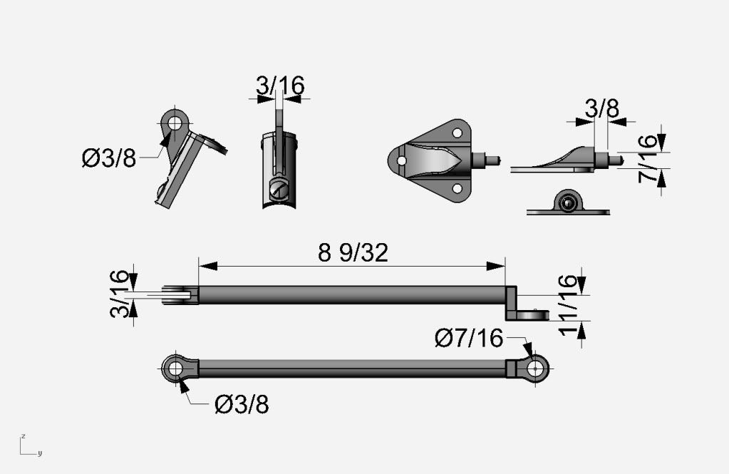
Force the struts into the correct locations and orientation: This requires sufficient play in sockets & tube to make an adjustment of a double bend, width approximately 1/4”. The socket & lug forgings are solid and tightly specified with given tolerances. No play there. The tube, 8 9/32” in length, is of stainless steel with an outside diameter of 0.5” and a wall thickness of 17G (0.0562”). Any fitting of these support struts in service is clearly intended to be by hand. Geoff’s comment here is “no way can a mere mortal bend that tube with finger pressure….”. So this possibility fails.
Easing the mounting holes: Geoff reminded me of the mostly humorous tension between the Drawing Office and the Production Dept. Easing was the first call when things did not fit as so often occurred. Of course, these days with 3D CAD such tension no longer exists:). Well aware of some of the deficiencies of engineering drawings and the need for such adjustments, I’m not sure if they will be adequate in this case. In 4/N.796 the socket bolt holes of the strut are given with tolerances for the lower socket 3/8 +/- 0.00025” and for the upper 7/16 +/- 0.00025”. The mouth of the bottom strut socket is given +0.005”/-0.000”. Easing to get the strut to fit fully with its upper and lower lugs needs an angle off the vertical of greater than 1.22 degrees. This angle requires easing of a size much greater than these tolerances. So in the abstract garden of my CAD, it looks as though easing itself cannot do the job.
Inconsistent versions of the Avro drawings: When I looked at the last amendment date on the various drawings, there seemed to be a real possibility that the problem at least was here. Here are the drawings and for each up to their last three amendment dates:
N.829, G.A. of armour & seat , 15-6-42, 4-1-43,10-6-44
13/N.771, Seat top plate, 27-7-42, 20-5-49, 8-11-49
2/N.796, Head armour plate, 6-8-40, 4-5-44, 23-1-46
4/N.796, Strut, 11-5-42, 18-10-43, 18-1-44
5/N.796, Bottom lug – forging, 7-10-43
5/N.796, Bottom lug, 12-5-39, 23-11-49
7/N.796, Top lug – forging, 5-10-43
7/N.796, Top lug, 16-5-39, 15-8-49 (illegible)
5/N.796 & 7/N.796, the top & bottom lugs both last modified in 1949 look to be good candidates for inconsistency. But they both use the original forging drawings issued in 1943. I believe the only changes can have been the depth of machining the forgings (about 1/16”) and the tolerances.
Probably the most interesting amendments were those to the head armour plate between 1940, 1944 & 1946.
Does anyone know what changes were made to the head armour plate between these years?
Mike
Wow, never seen that before!
Forward lift generated by the prop blades v drag of the airframe = prop blades curved forwards.
Am I correct?
Mike
Woe is me
Steve, have a heart for some of us who live in weird places such as South America and suffer from that ghastly system of CD & DVD regional codes. I’ve tried to reset my own player without success. So I can’t play your DVD as I understand it is coded for the UK etc.
It looks a beautiful film.
Mike
A case of quick & correct thinking

My Dad loved skiing in the Swiss Alps and used to go for weekends to St Moritz. When the weather was good he used to fly in G-AWOE to Samedan, an aerodrome very close to St Moritz. Samedan is deep within a valley closely surrounded by high mountains and there is space for only a tight circuit.
Unfortunately the weather was often bad and the train journey he had to take rather than fly took up too much valuable skiing time. So to fix it, he installed a radar in G-AWOE together with a camera mounted to take photos of the radar screen. He took many, many photos of the radar shapes of the mountains around St Moritz to the point where he could safely recognise the the Samedan valley from above clouds and safely descend through cloud to commence his landing pattern. I always just a bit worried by this as the fault free life of the radar was only 300 hours. But he was happy.
Unfortunately, he could not cover the whole of the Swiss Alps, Anyway, one day, returning from a skiing trip and flying over 10/10th cloud, he lost an engine. I think the carburettor heating had failed. He was high and couldn’t maintain that height on one engine. So he was forced to descend through cloud into a valley he didn’t know.
Nasty, Swiss alpine valleys have only one exit and there are only two directions to fly in these valleys, say North or South. If he chose wrong, opposite to the valley exit, he would be squeezed by the rising floor and narrowing sides of the valley and, since he couldn’t climb or by that time turn round, there could be only one ending on a mountain side.
He spotted a small river or stream in the bottom of the valley and noticed a weir. The turbulent water flow downside of the weir was the solution and gave him the correct direction to fly to escape from the valley.
Great perception and a cool head, I think.
My great thanks to all who have so generously offered their condolences
Mike
My dad, yes, he was a giant. I can’t really get my head together at the moment. Thomas, thank you so much for your condolences.
Yes, David. The future of G-AWOE, his Aero Commander 680E, does worry me. John made so many mods to the aircraft to suit his own needs. I’d like it to fly again; but I’m not too hopeful. Any suggestions?
Mike
Thanks, spitfireman. There are two arguments here.
Do Heritage-Images own the copyright? I very much doubt it. If the photo is genuine and not constructed, they would have to show they purchased this right from the original photographer or their heirs. Judging from the flight line, it was some RAF person or airfield worker. In those days, little value was placed on this sort of thing. Incidentally there are much better photos of this tragedy.
And then the disease of intellectual property rights which is destroying the free interchange of knowledge. Why should I be lauded for freely publishing images of my work when my intention was primarily to attract constructive criticism? Without which I am lost.
Mike
Could I ask why there is such a grotesque copyright symbol overlaying the Vulcan image?
If the image is real and not constructed, I very much doubt if such a copyright is owned by whoever published the image.
This business of intellectual property rights has gone well over the top. Bluntly it disgusts me.
Mike
Problems with Lancaster pilot’s floor and equipment
A great deal of effort has gone into making these 3D CAD drawings a faithful copy of the original as given by Avro drawing 2/C.1959, last amendment date 10th Feb 1945.
State of Avro 2/C.1959 Drawing
In contrast to many others, the state of the drawing 2/C.1959 is good; but shows hand-written corrections to the location of the secondary pulley for the rudder trim cables on the floor which, unfortunately, obscure the original values. There is also a labelling error which ascribes the right-hand seat under-frame foot to the flap valve. And then the problems described in this paper. Overall, I do get the impression that Mr Chadwick was away the day this drawing was made.
Equipment List
The equipment mounted on the pilot’s floor in the 3D CAD model are:
Pilot’s seat under-frame showing the mechanism for raising and lowering the seat
Trim control gearbox tower
Pilot’s glycol hand pump
Fuel jettison control
Carburettor intake heating control

View from above on port side at 7 o’clock with 12 o’clock being in the direction of the nose.

View from above on starboard side at 2 o’clock with 12 o’clock being in the direction of the nose.
Glycol Hand Pump
Fuel Jettison Control
Carburettor Intake Heating Control
Trim Control Gearbox
A Can of Worms
From A.P.2062 A & C Vol 1, Sect 1 Engine Controls, we have:
“22. Carburettor air intake control. – These shutters are hydraulically operated. On early aircraft the control lever is mounted on the floor below the navigator’s table and behind the radio set. On later aircraft the control is brought forward and upward to the port side of the pilot’s floor.”
Moving the carb heating control seems to have opened a can of worms; finding space to fit the trim tower, the seat and the carb control in a line across the pilot’s floor.
In following 2/C1959 two problems were found:
1. Following exactly the given location for the trim control gearbox tower, the two mounting feet closest to the aircraft centre line are far too close to the inner edge of the floor; enough to make an insecure mounting. There is photo evidence that the mounting feet did extend beyond the edge of the floor.
2. The seat centre line is shown to be offset inwards by 0.85″ from the control column centre line AND angled off 2.18 degrees anti-clockwise looking from above and forward. This was a definite surprise.
Unless the seat orientation is measured directly on site, it is difficult to know whether the offset and angle off have been implemented on any of the surviving airframes. They could have been mods implemented in production after Feb 1945 or not implemented at all and so don’t represent wartime aircraft. The 3D CAD model gives an opportunity for experiment to find the reasons for the mods which might give a clue as to when they were implemented.
Seat Offset Solves Carb Heater Control Fouling
Orienting the seat under-frame on the control column centre line without the 0.85” offset and without the angle off, causes the seat ratchet to foul the carb heating control. The offset solves the problem; but the angle off on its own does not. That puts this mod sometime in 1942/43 if not before.
The problem
The solution
Screw Loose
The dimensions given in the Avro sheet, very carefully followed, locate the two inner screw holes or mounting overhanging the floor edge; as in this drawing:

Moving the trim tower 0.2” outwards takes the screw holes of the mounting feet to the rivet line of the floor, as here:

Conflict! Or the Angle Off comes to the Rescue
Moving the trim tower 0.2” into the floor puts the two inboard screws in a sensible location. But we then have conflict between the right-hand front seat under-frame leg and the left-hand front mounting foot of the trim tower. The angle off of 2.18 degrees saves the day.
The problem
The solution
There are wartime photos which show some overhang of the two outer feet of the trim tower over the edge of the floor together with some crude chopping of the seat under-frame right-hand front leg & base. So it is possible the angle off of 2.18 degrees was a later mod than the seat offset. Perhaps it occurred in production 1944/45. But as yet I have not been able to obtain definite proof by actual measurement.
I’m in the Right Ball Park
Here is a photo of a real trim tower. See the gouge in the body of the tower. This was cut out to allow space for the seat under-frame cross member.

Here is my trim tower

The correspondence of the gouge in my tower with that of the real one does suggest that I am talking sense. My gouge was cut out with a Boolean operation after I had done all the previous work.
Just a final point, there is so much to do getting the basic drawings done that I have not yet had time to learn the sophisticated and powerful rendering software that would do marvels with the lighting, the materials and textures. I have used only the most basic functions of the rendering software.
Mike
Perhaps these analyses are just a bit over the top
Could it not just be that it takes a heck of a lot of time to do a good job with many false starts?
In my tiny way, producing 3D Cad of the Lanc, I don’t want to publish or let bits of it be seen here until I’m happy with them.
Other issues: distraction from the job, negative and non-constructive criticism etc.
Maybe?
Mike
For me, first the construction and use of the jigs, then the use of presses to make formers.
But really the whole technology to the greatest level of detail you can manage.
David, thanks a million (about right!) for publishing this photo.
Mike
I’m slow today
Smirky, I’m still not sure what you mean. The following is my understanding of the structure in this area:
The front windscreen frame is fixed via the gussets mentioned previously to the top of the box section of Former/Frame E and the cockpit side rails. Possibly also to the top of the top stringer running between Former/Frames E, F, G.
The bare instrument panel is fixed to the rear of the box section of Former/Frame E. The top of the instrument panel is flush with the Former.
The only thing left to my understanding are the exterior strips for the nose of the windscreen frame as arrowed (faintly) in the attached photo.
Please come back to correct me.
Mike
Formers & gussets
Smirky, frames 17,18,19 looking aft have the right sheet gauge 18,10,10.
The only problem is that my source giving the direction of the frames has 17 & 18 facing aft as per your photo; but 19 facing forward. I think I’d accept an error in my source. It is a low grade scrap perspective drawing. Add to that, frame 17 from original documentation has a radius on the corners of the frame of 1/8″ rather than the 13/64″ shown in the drawing I included in my last post. That squares better with my first attempt to extract dimensions from your photo.
You mean the triangular cross-section gussets fitted along the top of frame E that take up the angle of the front deck to give a horizontal base along the width of the windscreen?
Since my original intention was to do the nose section stopping at frame E, I haven’t yet done a search for documentation of these. However Malcolm Goosey sent me two splendid photos of his casting of the gussets in February. For my sake, you are welcome to these. But I’d better ask Malcolm’s permission. Send me a PM with some details of yourself and your project that I can forward to Malcolm.
My best wishes
Mike


 Sign In