Sorry, I can’t help. I have my own question as well.
For Avro parts, was the assignment of part numbers arbitrary in relation to the corresponding drawing numbers?
Is there any way, given a drawing number, to derive the part number & vice versa?
Mike
Many thanks, Peter.
Please, could someone give a link to this photo.
Mike
Paul, thank you. I think you’ve given me the key
Some paragraphs from http://www.raf.mod.uk/rafvalley/aboutus/4ftshist.cfm
“In the early 50s, the purpose of the Advanced Flying Schools had been to provide an intermediate step for aircrew between the Flying Training School and the Operational Conversion Unit, thereby ensuring a smoother transition from training-aircraft to operational types. The AFSs had also performed the earlier role of the Advanced Flying Units in that pupils trained with the Empire Training Scheme in Canada and Southern Rhodesia were retrained in an European environment.
The restructuring of the RAF flying training scheme necessitated the renumbering of the AFSs so that on 1 June 1954 No 205 AFS at Middleton St George, Co Durham, operating Meteor F4s and T7s was renumbered No 4 FTS. Commanded by Gp Capt H S Darley, DSO, the Unit provided many National Service pilots, mainly undergraduates, with their first taste of jet flying. In fact, the Meteor proved to be a great trainer and matured the young pilots in a remarkably short time. In January 1955, following the introduction into RAF service of the de Havilland Vampire T 11, 2-seat advanced jet trainer, the School’s role was changed. Pupils already qualified for their flying badges, having first completed their 130 hours basic flying training in the piston-engined Provost T1, came to No 4 FTS for a further 110 hours of advanced training on jet aircraft. No 100 (Pilot) course was the first course to complete their training at the School under the Provost/Vampire scheme and graduated in September 1955.”
“In the early 50s, the purpose of the Advanced Flying Schools had been to provide an intermediate step for aircrew between the Flying Training School and the Operational Conversion Unit, thereby ensuring a smoother transition from training-aircraft to operational types. The AFSs had also performed the earlier role of the Advanced Flying Units in that pupils trained with the Empire Training Scheme in Canada and Southern Rhodesia were retrained in an European environment.”
Thanks to your info “VT232”, I’ve a ref to the accident report “BT 233/248: Meteor 4, VT232: near Middleton St. George, Durh., 5 Nov. 1954” in the National Archives. The report is not digitised, so cannot be downloaded. There is a difference in the date, 5th Nov not 15th Nov.
I think that it is now 99% certain that Dickie is Richard Anthony Collingwood and the date of the accident is 5th Nov 1954.
The main questions in my mind now:
1. When did Dickie join 205 AFS or 4 FTS?
2. What was the training syllabus during that period?
3. What are the main points of his RAF career? Was he a national service entrant or otherwise? When was he commisioned? etc.
Mike
Careful, Fluffy’s list of codes are for Avro drawings, not necessarily for part nos. I suspect part numbers use different AM codes; but I can’t demonstrate it at the moment.
Paul:
It is the aircrew/groundcrew we should really remember.
Agreed. But can we add tool setters & jig makers to the list?
The courage of aircrew, the commitment of ground crew, those who implemented & made the technology.
It looks as though I have 15 years to catch up.
I’m using Rhino and am hitting memory limits.
What software are you using? Are you using a 64 bit system?
My biggest challenge at the moment are the multitude of intersecting fillets that are found on most castings etc. Basically, I haven’t learned how to deal with them at all. Great grief!
Any suggestions?
Mike
Sounds as though you live in San Isidro, Bob. Hope the mosquitos are not too ferocious. I’m near Coronel Suarez only 600 km away.
I’d love to talk Lancs & Lincolns in Argentina if this is up your street.
Mike
Somewhere around 1950, a pre-built Frog ‘fighter’, rubber powered. You mounted it in the box to wind up the elastic. It looked a bit like a Supermarine S6 without the floats. I seem to remember that it had an undercarriage and the wings unplugged from the fuselage. Did anyone ever get it to fly?
Many thanks. No excuse needed.
TerryP, thank you very much for these and for the re-arrangement of the images.
I notice that the end of paragraph 33 & para’s 34,35,36,37,38 are missing. This suggests there is a page between F.S./4 & F.S./5, strangely enough.
I think it might be image 10 in your numbering; between your two batches.
What you’ve given us is great. If there is the slightest chance you can give image 10 as well, that would be even better.
Mike
Slow progress
Progress is slow; but some things come out nicely.
Here is the front countershaft gearbox. It is used to transmit the pilot’s engine & prop commands via straight rods and (bycycle!) chains from the centre controls just below the instrument panel. The gearbox gives a change in direction: down from the pilot & then back through the main floor to near the main spar where there is another such gearbox which changes direction again into the wings for the engines etc.
Here is a view of the gear trains themselves & their supports. There are two main shafts, forward & rear. The control inputs go to the three gear arrangements in the left of centre. The rear arrangement is split in two, left & right. Each arrangement has nested hollow shafts which transmit the rotation to left & right respectively. SO that transmits commands to individual engines & props. The forward shaft carries commands which are not specific to any particular engine or prop. The output is on the extreme right. To the rear of that are systems of idler wheels. For reasons not yet discovered, this system of idler wheels reduced the height between the chains, giving a shallower gate into the main floor.

Here is a view with the covers in place. Above, to left of centre, there is an area uncovered with two vertical flanges. This is where the rods/chains from the pilot’s controls descend from just above the pilot’s floor and are cased in a box which attaches to the flanges.

Here is a rear view. The rectangular plate with flanges behind the input gears is a stiffening plate for the bomb door jack anchorage point just the other side of the bulkhead.

Here is a view from the front of the gearbox located on the bottom bulkhead of former E. The bomb bay observation door and various cable & hose fairleads can be seen.

This has nothing to do with the gearbox. It’s here because I like it and it was a pig to draw. It is to a much larger scale than the other drawings here. In the drawing showing former E above you can just see it peeking round the rear edge of the former about half way down the bulkhead. It is the bomb door hinge support bracket.

Of course, some of the original drawings are inaccessible or lost. So I had to make some assumptions & simplifications. But apart from these stated below, all the dimensions are correct to a few thou. You could, if you were unwise, build a real gearbox.
Assumptions:
The forward gears, shafts & bearings have the same dimensions & pitches as their rear counterparts.
The idler gears, to the right rear from the front, have the same pitch as the larger gears.
Simplifications (in the interests of reducing computer RAM usage as well as lack of info):
The bearings are greatly simplified. I could have added more detail to these but computer resources are not infinite.
I have not drawn the welds which join each gear wheel to its nested shaft.
I have not drawn the full multitude of screw & rivet holes except for a few which were used by me to register the location of other parts; again for economy of resources.
I have near enough completed the other side of the bulkhead. The main item that side are the bomb door jacks. I’m reasonably happy with the jacks themselves. But I had to invent the swivel joints at the top of each jack; also the hydraulic hose connectors on the body of the jacks.
Here it is:

If any kind person has a good clear photo or an Avro detail drawing of these swivel joints and/or the hydraulic connectors and can send me a copy, I would be over the moon.
The word here about surviving Fraser Nash production drawings is a bit depressing.
I would dearly like to have copies of any such dimensioned drawings of the Lanc installed FN5 nose turret. Any chance?
Mike
A bit of a problem
It seems that PA474 does not have an original head armour plate.
Has anyone got such an original plate in their workshop or storeroom and can do a couple of easy measurements for me?
Just a taster, here is a wire drawing of the work on the front centre section from formers E to 3 with a trial former D port side.
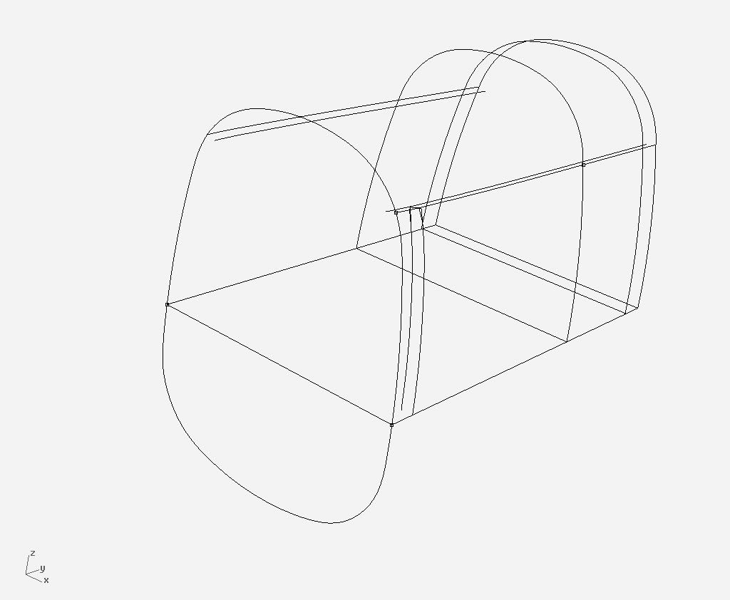
The critical point here is the way the cockpit rail deforms to match the different profiles of formers E and 1. It’s taken me some 18 months to find an authoritative solution from D.3336 etc.
In front view the rails are rotated inwards 14 degrees AND in plan view curved inwards towards the front by just under 1 1/2″.
Mike
Stuart, I’m going to ask Tim to do that. But if anyone else has a chance to check for me, please. There are some disadvantages living in Argentina!
The critical things to check are the three dimensions:
1. the width of the head armour plate. Is it 16″ or is it 15 5/8″?
2. the distance between the strut tube centres at the top. Is this 17.475″?
3. the distance between the strut tube centres at the bottom. Is this 17″?
If these dimensions are respectively 16″, 17.475″ & 17″, then an eyeball description of the strut. Is it vertical in front view? & if so how on earth can it be so with these dims? If it’s not vertical, where is the bending or easing which allows the sockets to fit onto the lugs?
If those dimensions are not these, how do the struts, sockets & lugs differ from my drawing?
Don’ forget about the top lug behind the armour plate. In the configuration shown in the Avro drawing, the body of the lug must line up with the edge of the armour plate. It can’t be inset. Otherwise the top socket of the strut would foul the armour plate.
Stop now, Houlder. Stop! Or someone, ship me by Fedex a whole Lancaster. Better two of them so I can see how the changes went.:D
Mike


 Sign In