A bit of reality checking

distance between former faces and dimensions of the longeron itself
D.2417 “Front Turret Support Frame”, last amended 26-03-1940
height of longeron top face above datum at front face of former K
D.2434 “Front Turret Support Frame Joint at Former K”, last amended 15-09-1942
height of longeron top face above datum at front face of former J
D.2444 “Joint – Turret Support Frame To Former J”, last amended 20-09-1940
height of longeron top face above datum at front face of former H
D.2432 “Front Turret Support Frame Joint at Former H”, last amended 28-07-1939
height of longeron top face above datum at front face of former G
D.2431 “Front Turret Support Frame Joint at Former G”, last amended 09-01-1940
height of longeron top face above datum at front face of former F
D.2308 “Nose Former F”, last amended 05-05-1944
height of longeron top face above datum at front of vertical flange of former E angle
D.2307 “Nose Angle Piece At Former E”, last amended 08-08-1942
There’s a big spread on those amendment dates. I guess for full confidence I would need to see Avro drawings for all the prior amendments.
But that’s not possible now. We are lucky to have what we have.
Mike
Who did it?
Those notches! They were drawn into Avro D.3272 as below:

So the guilty were among: D.N.T, A.C, J.D.T, H.D, Astley etc These were the signatures of the draftsmen issuing amendments.
The notch for the blind flying panel on the other side is also shown. But the 3rd circular notch is NOT shown and that one being close to the one shown here must have weakened the structure.
I’m not sure of the material used for the former extrusion. The only reference i have found to date is SS 3075 sheet 5L. I’m sure it was some form of steel. So, perhaps, the windscreen structure did not add significant strength to compensate.
A crazy thing to do just for the location of a switch & a dial.
Mike
Bless you, Lazy8. Yes, your photo does seem to show notches.
Also, your photo reminded me that I had tucked away a similar shot as here:

Yes, notches confirmed. That surprises me.
Thank you, Lazy8. My brain is rapidly turning into porridge. I need a break from Lancasters, believe it or not.
At the very least you’ve saved me from a lot of unnecessary work.
Mike
Here’s a wireframe image of the above which might make the problem clearer.

Greg, Geoff has answered very well your query about the front righthand cutout of the pilot’s floor. To get some idea of the complexity look at my posting in this thread for 23rd Nov 2012, post 47.
For the lefthand front cutout. it’s not just the pressure tank in front of former E. There’s a whole lot of gubbins to the port side & underneath the pilot’s floor that needs access. Among these, the autopilot system. I do have some good photos and the Avro drawings for all this.
I’ve been puzzling over an anomaly with Avro drawings D.1746 and 8 & 9/D.1675 for some time. A very kind person gave me Avro drawings of the packing pieces round the top & sides of the former E extrusion which change its contour. So I’ve got a very good chance now to sort out the anomaly. Here are a couple of pics to show these packing pieces:


And here is a poser produced by that fine photo of the sad original state of FM159 that you published, Peter. Many thanks for that.

A I say, any ideas.
Mike
Some very good questions, Greg. I’ll need a bit of time to answer them.
Basically the question of the trim tower seems to be a cludge to allow the carb heating control to be moved next to the pilot. Previously it was on the nav’s floor. So there really isn’t enough space for the trim tower. Anyway I’ll look seriously at your questions; but not just yet.
Mike
A check of these, please
Can anyone see any problems or omissions?
Additional furniture hs been added to the pilot’s floor. The trim tower, the glycol hand pump, the fuel jettison control and the carburettor heating control.
For the seat and seat underframe, I have omitted the bowden cable to release the harness lock and the tension elastic to tension the seat elevation hand lever. Both these are above my skill level.


How to draw the Lanc FN5
I’m very lucky with my 3D CAD project on the Lanc. Apart from a couple of instances, every part I have drawn including all brackets and rivet holes etc has been backed up by one or more Avro engineering drawings. In my work I have tried to maintain the standard Avro precision of 1/64″. The following pic illustrates the level of detail of the work. This is a view of the top of the pilot’s seat showing the harness flanges with their lockable socket, There is a bowden cable running from the socket just behind the flanges to the left in this pic down to a locking/unlocking lever on the starboard pilot’s armrest. I’ve not drawn this cable since doing so is beyond my skill level for now.

The project is to complete the nose & front centre sections to this level of detail. Again, apart from one or two smaller parts, I am lucky enough to have all the 2D Avro engineering drawings I will need. With one glaring exception!
The front turret. It’s seems that the Frazer-Nash drawings no longer exist on the planet. There are plenty of photos and I have been offered the AP. But taking dimensions of visible parts in photos is very unsatisfactory. The AP would help of course. But the amount of guess work would be so great that any drawing I made of the turret would be incompatible in standard with the rest of the project. Probably in this case it would be better to leave off the turret.
Rather sad, isn’t it. Is this really the case. Are there really no engineering drawings left? Is there anyone who can help me?
The project is very definitely non-commercial. I’m too old to concern myself with either lucre or fame.
The other problem is that I live in Argentina and return to England very rarely. The thought of a 37 hour journey, most of the time squirming in those ghastly airline seats, plus the hassle of passing through security in Heathrow is really off-putting.
Can anyone help me at all?
Mike
pilot’s seat position now corrected
In plan view the centre point of the control column box should be 11″ to port of the aircraft centre line.
Again in plan the centre point of the box should be 10.83″ aft of the rear face of the former E extrusion.
In side elevation the top surface of the pilot’s floor should be 18.38″ above the fuselage datum.


Larger images can be obtained through the PhotoBucket links.
No Cees, they haven’t. But anyway I’m thinking of a 1/8 scale 3D printed version – Well, I thinking of it.
It would be rather glorious – just the nose & front centre sections.
Red face!
Problem solved, I think, Peter.
I forgot the wretched connection links on the underframe front levers as arrowed here:

I’ve left out the bushes on the links & levers..
For perfection, I should match the hand lever to the seat height. I’ll leave that for another day.
OK now?
Mike
There may be a difficult problem here resolving different mods & and even museum lash-ups , Peter.
Look at this drawing with the side struts shown. It is a faithful reproduction of Avro 4/N.796: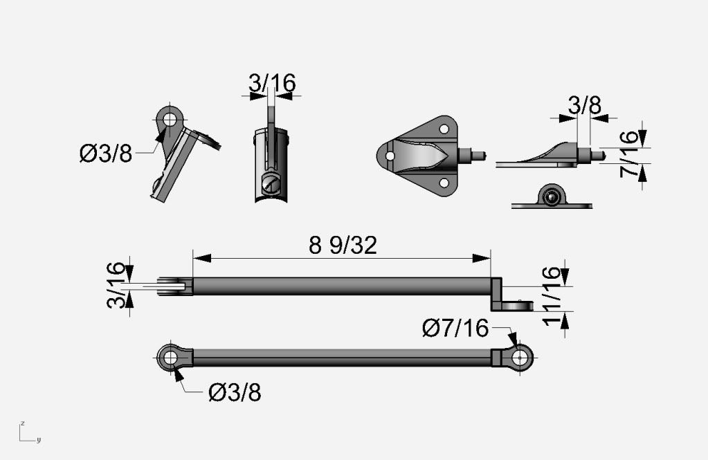
Compare these side struts with those shown in the photo you give here:
I would say the strut shown in the photo is a lot longer than that given in 4/N.796.
So is the strut shown in the photo a real Avro part or is it a museum construction to make the angle of the head armour more acceptable?
I’m not sure at all. I have difficulties with the set of Avro drawings relating to this. I found an inconsistency I could not resolve.
See my posting http://forum.keypublishing.com/showthread.php?118860-Has-anyone-built-a-Lanc-seat-I-got-a-problem&highlight=MikeHoulder
Unfortunately, the head armour and its struts etc were among the first things to be discarded in 1945 and no one as yet has pointed me towards a genuine set. I’m probably in the middle of inconsistent (different mods) Avro drawings.
As regards the angle of the head armour, see this section from Avro N.829
[ATTACH=CONFIG]219997[/ATTACH]
This suggests the angle of the armour is correct; but I have the angle of the seat wrong.
In this case, my error is to assume the angles to the horizontal of the front & rear levers of the seat underframe were equal.
These levers make the join of the underframe to the seat itself.
I’ll have to study this more deeply.
Thanks, Peter.
Mike
Summary of work so far
The location of the pilot’s seat and deck is right laterally; but I need to re-check the location fore & aft & height.
The top line of the dimension boxes is the max height of the canopy above the cockpit rail top surface.
Formers 2 – 5 are not yet drawn. The cockpit formers 1, A, B, C, D’, D” & 6 are not detailed.


Sorry for yet another image of the bracket. But this view seems so bonny and, at least for me, rather thrilling(?).
This sits on top of the former K cupola ring and very firmly fixes it to the turret support longeron and the turret ring.
In this image it has been rotated to avoid having to change the light & camera positions in the CAD program(Rhino).

Also, I forgot to say that there are dimensioned engineering drawings available, drawn by myself, on the web site
http://www.lancasterbombers.net/BomberCommandHistoryForum/index.php
in the sub-forum ‘Lancaster technical drawings’. I hope to build up a set of reference drawings for the Nose Section and the Front Centre Section there, given time.


The centre of the former K ring does not lie on the datum line (side elevation), confirmed in D.2325. The only Avro info I’ve found is that at the former K position the top of the turret support longeron is 22.25″ above datum, confirmed in D.2434.
So it’s important to get this stack of brackets and angles right. These sit on top of the K ring and so give the location of the top centre point on the ring. Hence the ring centre is 1.50″ below datum according to my drawing.
Angle 15/D.2430 was difficult enough to draw. It must be a real pig to make.
Mike
Still at work!
I haven’t posted anything here on the project for a while. So here are some pics showing current work.
The stringers have not yet either been trimmed or fitted at their ends. Their termination at former K is a bit tricky.


 Sign In