Many, many thanks, Dave and Eric.
Mike
If I remember rightly, that’s not battle damage on N3277. It’s the self-destruct on the IFF or Pipsqueak systems.
Mike
Yes, remember the business of adding lengths of chord to balance the ailerons of a Spit or worse the use of a large tuning fork to bend the errant aileron. So precision could not have been quite so precise.
But, on the other hand, Bruce, I have been given a large set of photos showing the jigs and machine tools used in Lanc production. My guess is that locally they really were as precise as I’ve drawn or even better (mine are not perfect). I can’t see the same precision where large pieces have to be joined.
Again, on the other other hand, the location (and angle) of many rivets holes were not given. The phrase is “drill to suit part X/D.XXXX”. I’m inclined to believe that this copout was due more to the technical problems of drawing a 2D projection with the tools they had available.
So you pays yer money and takes yer choice.
For me, I want to make sure the parts fit together when I combine them.
Mike
Former 3 Top Joint
I want to get the cockpit rail done & dusted. The rail finishes at former 3. So I’m doing 3 now.
That’ll give me former E – cockpit rail – former 3 completed.
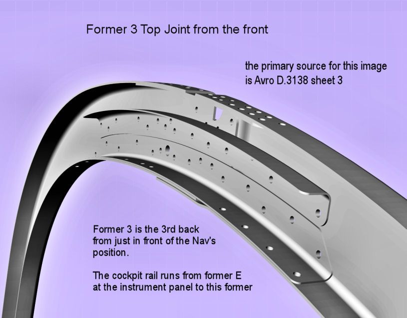
The joint strap has a clear function to bridge the gap caused by the cutout for the top centre stringer, no. 1.
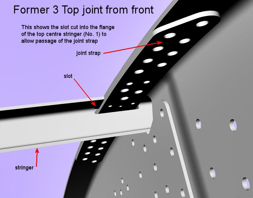
But then the strap has to pass through the stringer. So a slot is cut in the flange of stringer 1.
Would it not have been better to split the stringer and avoid the need both for the cutout in the top of the former and the joint strap? The stringer is weakened by the slot. So splitting it and fixing it to both sides of the former might have been better?
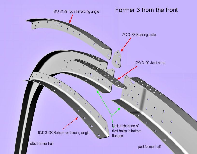
Given the cutouts for threading through the top stringer, the top reinforcing angle has a clear function. But what about the bottom reinforcing angle? I can’t understand why rivets were not used to join the ends of the bottom flanges of the formers. Look at the parts marked with green arrows in the 2nd image. If those parts had been riveted, then there would be no need for the bottom reinforcing angle.
Isn’t it great fun to second-guess the blokes who actually had the responsibility!
Mike
Constructing the profile for Former E
As regards the profile, former E is a cut down version of the standard FCS (Front Centre Section) former. The profile of this was shown in the last two or three posts. The top 25% by height of the standard profile are replaced with a new curve given by coordinates. You can see here.
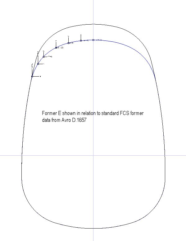
This shows the coordinates that are given in both the Avro drawings D.1657 and D.1916
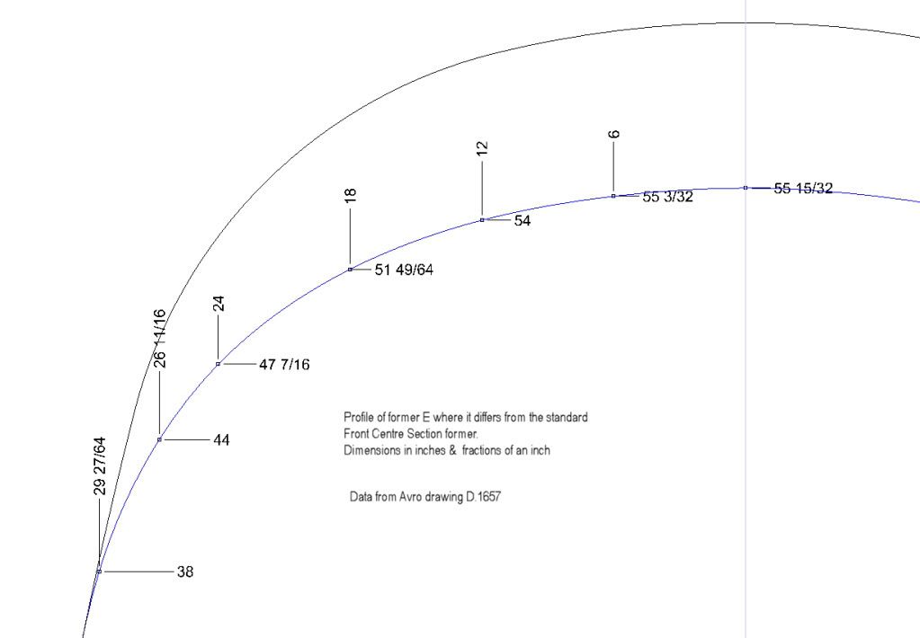
The standard former curve was divided into a large sequence of points, omitting the top 25% by height. A spline mathematical function was used to create the entire profile of former E using these points and those given by the coordinates.
Constructing the standard former profiles from former 1 to former 22. Part 2 of 2.
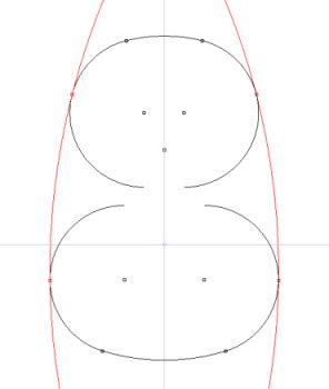
Here our objective is to find the arc of a circle, radius 216” or 18 feet, which makes a smooth joint with both the two arcs/circles, radius 22.5” on one side of the centre line. The position of the two small arcs/circle is known. The construction method used here is the same as used in part 1, but with a slightly different perspective.
Construction
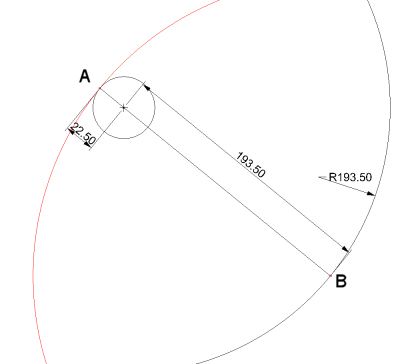
From any point A on perimeter the left half of the top arc/circle, draw a line to the centre of that arc/circle. The centre is known. Extend that straight line a distance of 193.5” to point B. The total length of the straight line is now 216” (193.5 + 22.5 = 216)
The first segment of this line, length 22.5”, is a line from the centre to the perimeter. Hence the tangent at point A is perpendicular to the line AB.
Now if we draw a arc/circle of radius 216” shown in red with centre point B, this will pass through point A. Again for any straight line from the centre of a circle to a point on its perimeter, A in this case, the tangent to the arc/circle of 216” radius at A will be perpendicular to the straight line.
So we have found the centre of a arc/circle of radius 216” whose tangent at point A is the same as the tangent to the small arc/circle at A. Hence we have found the arc/circle, radius 216” and centre the point B which makes a smooth joint at A with the smaller circle.
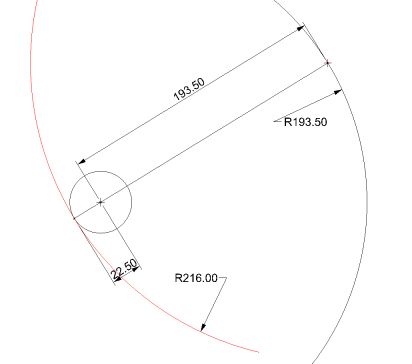
Now, if we choose another point on the blue curve, call it B’, draw a straight line from B’ to the centre of the small circle and then extend that line to another point on the perimeter of the smaller circle, A’. This line passes through the centre of the small circle so it is perpendicular to the tangent of the small circle at A’. The length of this line A’ to B’ is 216”. If we draw a circle, radius 216” and centre B’, the circle will pass through point A’. Since the line that fixes point A’ is from the centre of the new arc/circle, it too will be perpendicular to the new circle of radius 216” at A’. So both the tangents to the new circle and the small circle at point A’ will be equal. Hence A’ forms a smooth joint between the 216” arc and the 22.5: arc
But we chose point B’ arbitrarily. So any point on the blue curve of radius 193.5” can be the centre of a circle, radius 216” , which forms a smooth joint at a corresponding point with the top small circle.
All this applies equally to the bottom small circle and we have:
OK, we can find arcs/circles, radius 216”, for both the top and bottom small circles.
But we need it to be the same arc/circle, radius 216” with the same centre. Problem!!!
Easy! If you draw both the blue curves for both top & bottom small circles when those are in the correct position relative to each ,
You will find the blue curves intersect.
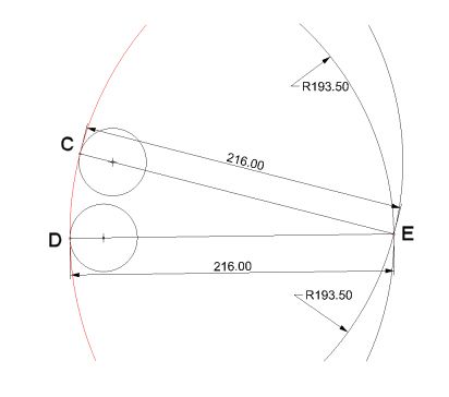
E is on the upper blue curve, radius 193.5”, so an arc, radius 216” centre E forms a smooth joint with the top small circle at point C.
But E is on the lower blue curve also, so an arc, radius 216” centre E forms a smooth joint with the bottom small circle at point D.
So it is the same arc, radius 216”, shown in red that makes smooth joints with both the top & bottom small circles.
Problem solved!
We have, using symmetry about the centre line:
Just chop off the bits of curves that we don’t need and we have produced the standard former profile.
With my CAD system I can derive this with super precision. But in general this is a much more precise way of defining the former profiles than the coordinate based system for the nose section formers.
With compass, ruler & pencil, all these formers can be reproduced on paper by hand to whatever scale is required by adjusting the numbers to suit the scale. In some scales the paper might have to be larger than normal to cope with the large radii 216” & 193.5”.
Next will be the derivation of the profile for former E.
Yes, Greg, you’re doing fine. Your coords for the 216 radius circle (-181 31/64, -8 7/64) are spot on for the port side side wall. For the stbd it’s (+181 31/64, -8 7/64).
Yes, the X axis shown is the horizontal datum line which is the top of the 3 inch floor. Particularly for Canadian built Lancs, the floor had a depth of 4 inches instead. I have not yet sorted out the implications of that.
The typical precision used by Avro throughout their drawings is 1/64. When it matters, say for a tolerance, they will change to a decimal form of at least 2 decimal places.
Here’s the rub. I’ve implemented the Avro method correctly with a great deal more accuracy than they could have managed at the time.
They give the width of the floor at the datum line as 68.78 inches. I presume, since they go to the 2 decimal place format instead of 68 25/32, that here it matters and no departure from this number will do.
The width at the datum in my drawing is 68.7301. 5/100″ less than stipulated. That’s too much to be ignored.
I don’t think there is any error in my work. I think the difference comes from the difference in drawing technology between then and now.
So, at present, I am trying to find the minimum change in the given numbers which generates a width on the datum of 68.78″.
So far, I think the offsets of the 22.5″ curves have to be increased. For the top, the centre of the 22.5 curve must lie on a line 6.03″ from the centre line (i.e. 6 1/32). Similarly for the bottom, the offset should be 12.03 or 12 1/32.
Mike
Constructing the standard former profiles from former 1 to former 22. Part 1 of 2
i.e. from the former just in front of the navigator to that at the end of the bomb bay.
Formers 1 to 22 have identical profiles. Call this the standard profile for the centre section up to the end of the bomb bay
The remaining formers towards the tail, 23 to 41, use an identical method but with different numerical values.
The numerical values for all are given in Avro D.1629 sht 2
The profile of former E is derived from this standard profile as will be shown.
The cockpit section and nose section formers, A to D, F to K, use a different system of individual coordinates to define their profiles
Standard Profile
The standard former profile is made up of a total of 8 curves, each being the arc of a circle. The profile is symmetric about the aircraft centre line. The joints between the curves must be smooth.

The top and bottom green arcs are known with radius 47.5” and centre at (0, 15.5) for the top arc and radius 63.5” and centre at (0, 28.5) for the bottom arc. The blue arcs have radius 22.5” but their centres are unknown. The side green arcs have radius 216”, 18 feet.
Construction:
The objective is to make a smooth joint between the arc of a circle, radius 47.5″, whose centre is at (0, 15.5) and a circle whose radius is 22.5″. The location of the centre of the small circle is unknown. But that centre must lie on a line 6″ to the left of the C/L.
There is a unique solution to this objective.
The first thing to do is to find where in general the centres of the small circle must line, ignoring for the moment the restriction.
A smooth joint between any two arcs or circles at least must have equal tangents at the point of joint i.e. the tangents to both arcs at the point of join must have the same gradient or angle.
We are talking here about circles or arcs of circles. So a line perpendicular to the tangent at the point where the tangent touches the arc must pass through the centre of the arc/circle.
Since the tangents are the same at the point of join, then the perpendicular lines through the centres of the arcs are the same also.
To be joined the small circle must actually touch the big arc. So in this case the centre of the small circle must lie 22.5″ along the perpendicular to the centre of the big arc coming from the point of join.
You can see this in the image here.

Notice that the centre of the small circle is 25″ away from the centre of the arc. So all points on the arc with radius 25″ will give the centre of a circle, radius 22.5″, which makes a smooth joint with the big arc at different points on that arc.
But there is only one point on the arc with radius 25″ which lies on a line 6″ from the C/L.
So now we know where to draw the small circle to meet the given conditions. With its centre at (6, 39 49/64). That gives us the following image.

The curves are symmetric about the C/L and I have included the bottom curves. These are found in exactly the same way, except that the big arc has radius 63.5″ and centre at (0, 28.5) and that the centres of the small circles, radius 22.5″, must lie on a line 12″ away from the C/L.

That leaves just the large side arcs to be found. This is done in nearly the same way, just a little more complicated. This will be shown later.
Cees, I have a number of Avro rib contour maps for the Lanc.
That won’t tell you at least directly what aerofoil sections were used.
But it should answer your question.
Of course the best quality and most readable ones are for the Lincoln.
But I’m hard pressed with a great deal of work on other matters at the moment.
If you need these, can you wait a couple of weeks or so?
Mike
I need to reduce the thickness of that front end stiffening plate. I don’t know by how much yet.
The Avro drawing of the stiffening plate at the other end of the cockpit rail is a better drawing!
Mike
The front end of the cockpit rail sorted out with its flanges.
The flanges themselves were relatively easy to do.
But not the top corner holes. Presumably these are to insert a spanner or similar tool.
It involved exploring a new area to me of the CAD software – projecting (or pullback) curves onto surfaces.
It really needs some theoretical explanation to use properly. One day I’ll look it up.
Here are the flanges and the holes.
Here’s an upper side view showing the big thick stiffening piece around which the flanges are wrapped.
This is a view of the interior of the front end of the rail to hang it all together.
Mike
Cockpit Rail
All the data here comes from Avro D.3336 port side & D.3337 stbd side.
This image is a rear perspective of the rail plus a table to plot the points to produce the curve.

Apologies for this one. To map the cross-sections to the wire diagram on the left, reverse them. Well, you can’t have everything.

A Meteor first intercepting a Canberra and then bringing it down, a bit unlikely, isn’t it?
Mike
Yes, I was fixated; but on the wrong problem. Any anomaly usually suggests an error on my part, as it does in this case. Look at the flanges at the front end of the cockpit rail below. The outer flange is wider than the other two which have the same width. In the Avro drawing D.3336, all three flanges are of the same width. In the upper and inside flanges the line of the screw holes is 5/16” away and parallel to the outside edges. But the miscreant, the outside flange, says the line is 1/2″ away from outside flange edge. But says me, the flanges have the same width and so this cannot be true – I’ll make it like the others with a distance of 5/16” – stupid!

I was fixated on the outer curve of the side support panel. For the profile curve of former E, there are good points given to define the bottom 2/3’s of the former. And good ones for the top 1/4 . The good bottom points are defined by the Avro system of drawing the standard fuselage profile. The good top ones are given in at least one of the Avro drawings for former E. But there is a gap of about 1/12 where the top curve given for former E runs into the bottom 2/3 of of the standard fuselage curve. There were an infinity of possible joins of the two curves. And I thought that the outer curve of the side support panel might determine the issue. Then with the greatest luck I found one Avro drawing for former E which gave me two points within this dark interval.
So the former E curve is now fully determined.
All this explains why I thought the problem to be important and why now I am not concerned with that outer curve of the side panel. I have one drawing which says it should be as I’ve drawn it, not following the profile curve of former E. And I have found no drawings otherwise.
But at the heart of this is the instruction at the head of every Avro drawing as below. Of this I am guilty even though many times in the past I have tried to drum it into my head.
Here is the joint without the stiffening piece. The outer holes are now fine.

And here is the joint with the stiffening piece in place.
On the overall issue of fixation, all I know is that I have had to redo work so many times because I have ignored an anomaly. Remember I am working bottom up. So a trivial error at the bottom level can throw things badly out when groups of items are combined together
Mike
Good news but with problems
The good news is that I have found a key dimension that I had missed or mis-interpreted in Avro D.3336.
It is the distance from the top outer corner of the front edge of the cockpit rail from the vertical datum, the centre line of the aircraft, at 26.92″. The perpendicular distance of this corner from the horizontal datum, the top of the floor, ar 44″ I had already known.
The front edge of the cockpit rail has three flanges with two rivet/screw holes in each flange. The location of the centres of all six holes is also given with respect to the top outer corner in D.3336. The other pieces involved, the side support panel & the stiffening piece each have the positions of the corresponding centres defined for the two holes on the inside and the two on the top. Since these must match with those of front edge of the cockpit rail, the location of these additional two pieces is also defined.
That’s the ggod news. But now for the consequences which are not so good.
Here is an image which shows the three pieces in relation to each other, giving the order in which they are assembled. Remember, the image of the front edge cockpit rail section show a slice through the very front edge of the rail which goes from former E continuously through the whole cockpit to former 3. The order of formers being: E, D, D’, C, B, A, 1, 2, 3. Note D, D’ are on opposite sides of the cockpit; one further forward than the other.
The image shows the rear view of the port side edge and there should be a cutout for the compass in the side panel. But I’m not bothering with this at the moment.

This shows the ggod news.

But now the bad news.

As a generalisation there are two types of Avro drawings: arrangement drawings without dimensions and engineering drawings with full dimensions. For all parts involved I have implemented faithfully the engineering drawings. I believe that now there is very little room for significant error. In particular, I cannot find a way in the engineering drawings to avoid the failure of the 3 items to follow the outside curve of former E + packing piece ‘de’.
On the other hand I do have an arrangement drawing which shows a curve on the outside edges for both the cockpit rail and the stiffening piece. I’m sure also that the high-lighted screw hole of the side panel should not be so close to the outside edge of former E.
Can anyone help to solve this conundrum? Perhaps with photos or a good description.
Mike


 Sign In